
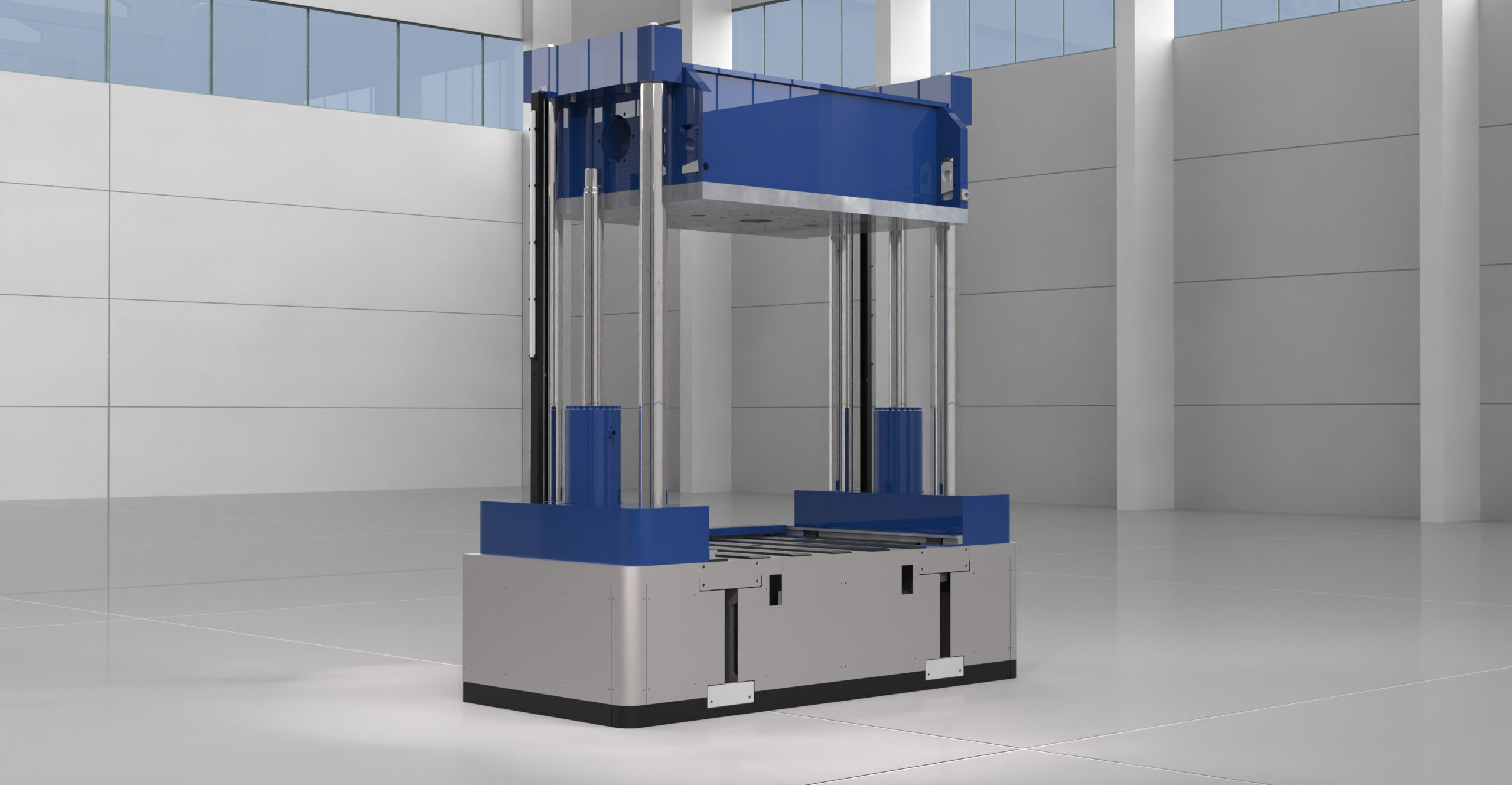
SPOTTING PRESSES FOR ASSEMBLY, ADJUSTMENT, CHECKING MEDIUM MOULDS AND DIES
BV 32E / 33E / 34E / 35E SERIES
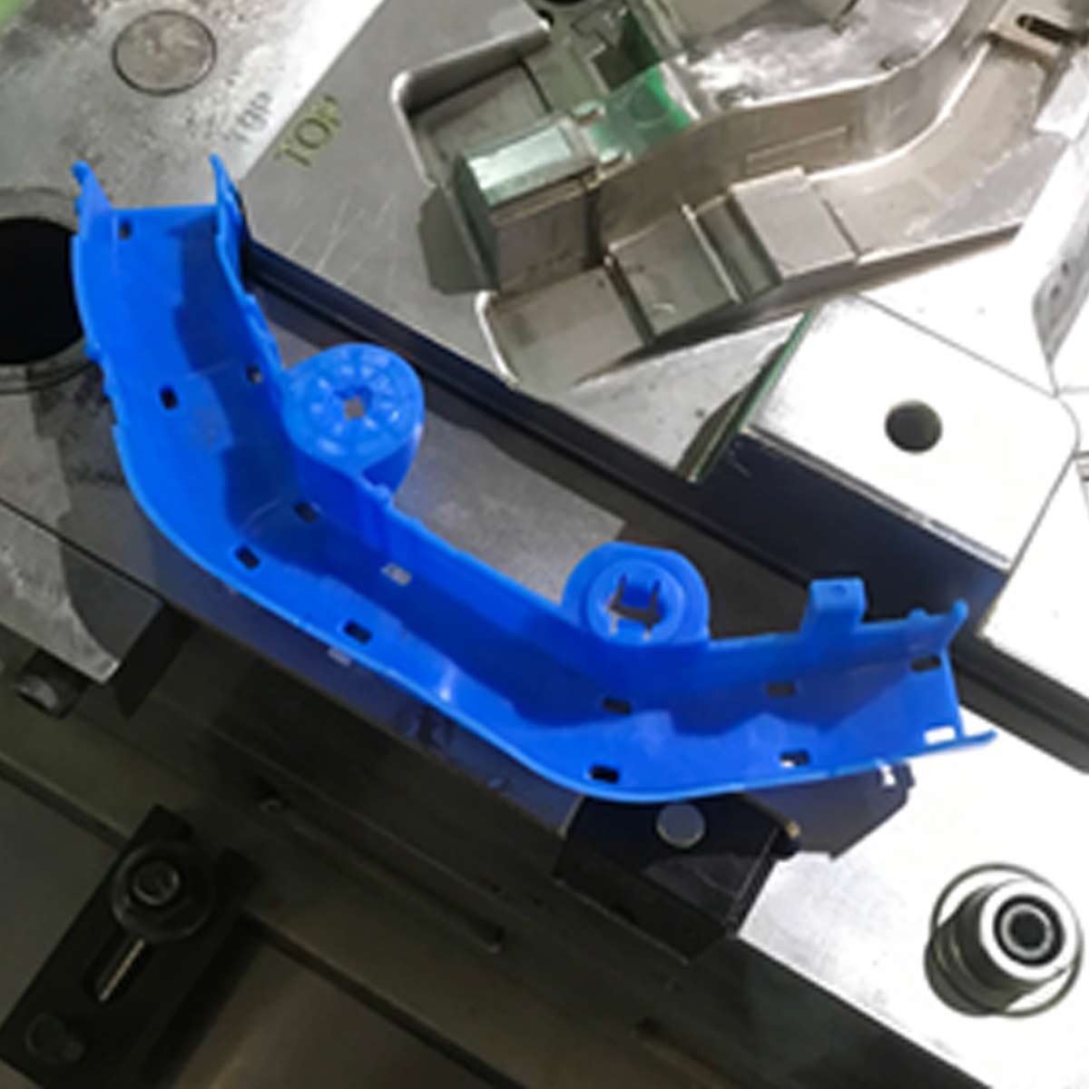
The press is used for splitting, adjusting, maintenance and try-out operations on dies and moulds (thermoplastics, die casting, thermosetting, rubber and blanking).
The BV 32 – 33 – 34 – 3 series is suitable for medium-sized moulds.
Two models are available depending on the platen dimensions:
BV 32E / BV 33E
Platen dimensions are 1.600×1.300 mm.
Clamping force is 1.200kN in the BV 32 E against 1.500kN in the BV 33 E, while is 1.500kN in the BV 34 E against 2.000kN in the BV 35 E.
The max. load capacity on lower plate is 16.000 kg, (minor capacity in the model with option -R 10.000 Kg or option -G/-RG 8.000 kg) while on the upper plate is 10.000 kg.
BV 34E / BV 35E
Platen dimensions are 2.000×1.500 mm.
The max. load capacity on lower plate is 30.000 kg, (minor capacity in the model with option -R 22.000 Kg or option -G/-RG 20.000 kg) while on the upper plate is 15.000 kg.
The difference between the two versions is the max. Clamping force, 1.500kN in the BV 34 E against 2.000kN in the BV 35 E.

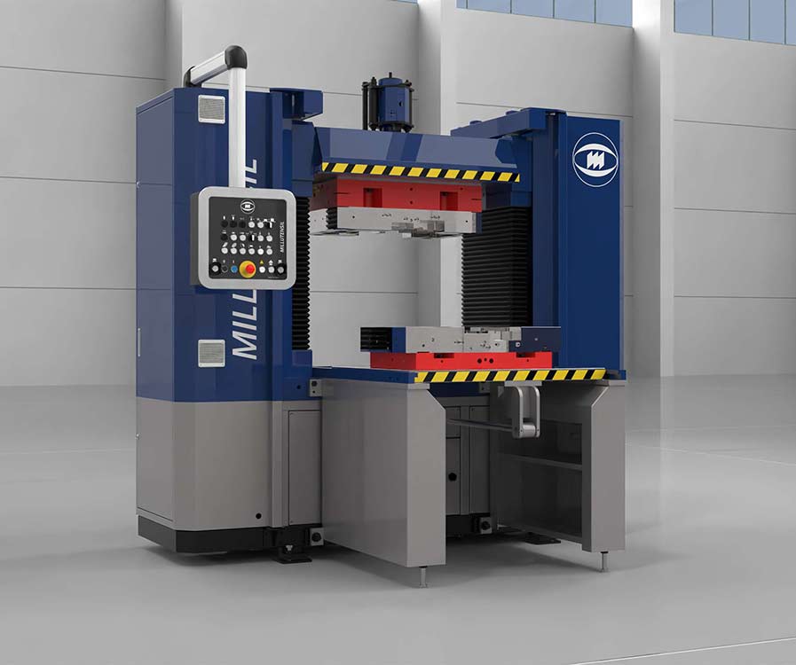
BV 32E – BV 33E – Platen dimensions: 1.600×1.300 mm
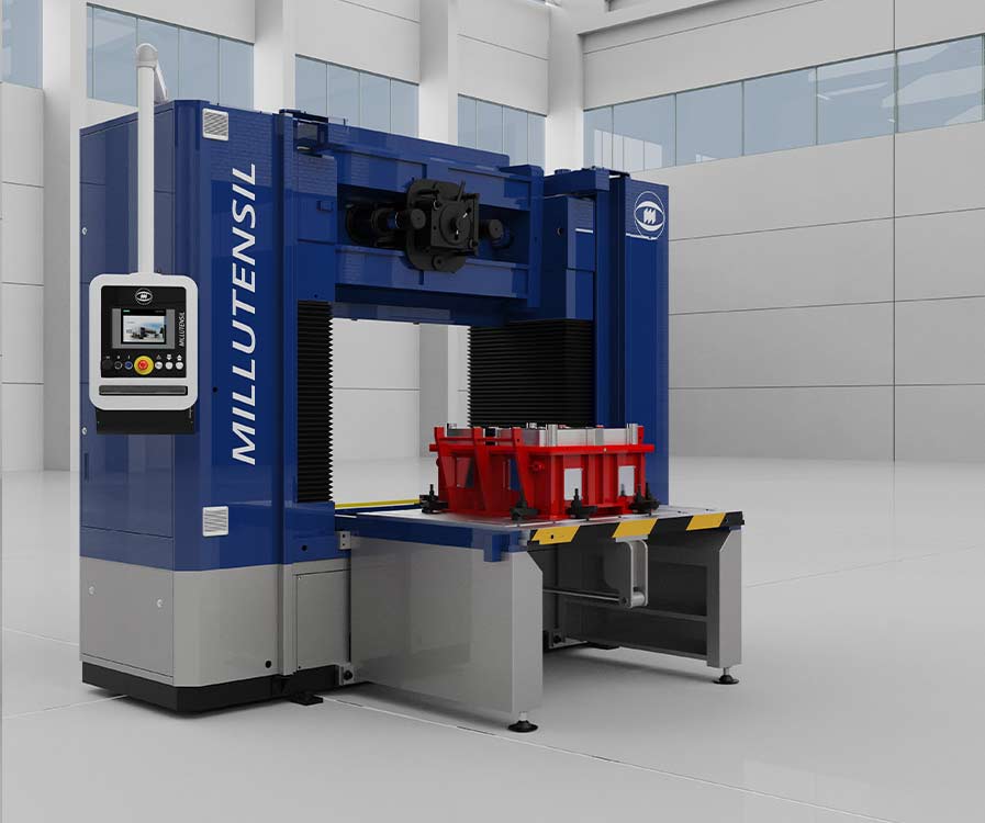
BV 34E – BV 35E -Platen dimensions: 2.000×1.500 mm
The very sturdy structure consists of a welded and normalized steel basement and cast iron baseplate. Hydraulic system is controlled by electronic servo proportional valves.
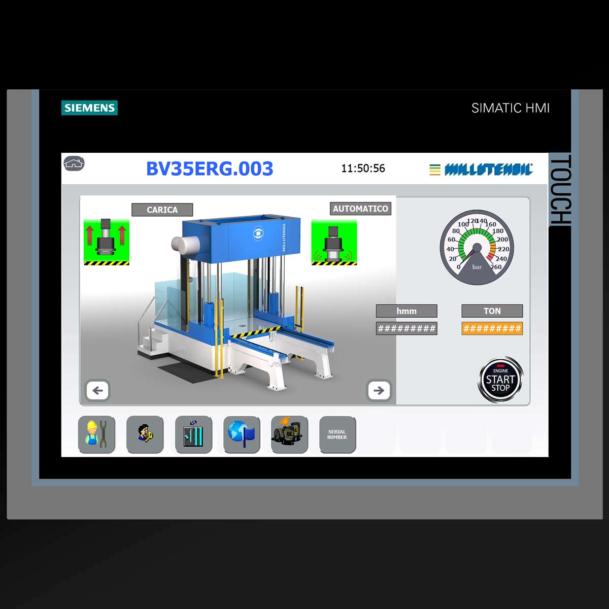
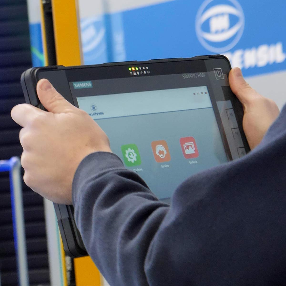
All E models are equipped with user-friendly graphics control panel, monitored through Siemens PLC commanded by Touch Panel installed in the pulpit station.
All components are purchased from well-known manufacturers, such as for example: hydraulic system Bosch-Rexroth, Hawe; electrical system Siemens, Schneider Elektrik, Phoenix Contact, Weidmüller. This guarantees a general good functionality of the press, and a quick procurement all over the world.
EC Declaration of Conformity and compliance with safety provisions in accordance with the current EC standards.
PLATEN MOVEMENTS


The upper plate slides vertically by hydraulic actuation on the four guide columns and can be overturned 360° through reduction gears. The upper plate clamping in the exact horizontal position depends on the four hydraulic actuated locating pegs.
The lower plate is hydraulically extensible, sliding on the base guided by ball bearings. It allows to draw the lower part of the die or mould out of the press into an effortless working position.
The lower plate can be optionally tilted by 90°.
All functions are comfortably performed from the touch panel.
VIDEO
FEATURES
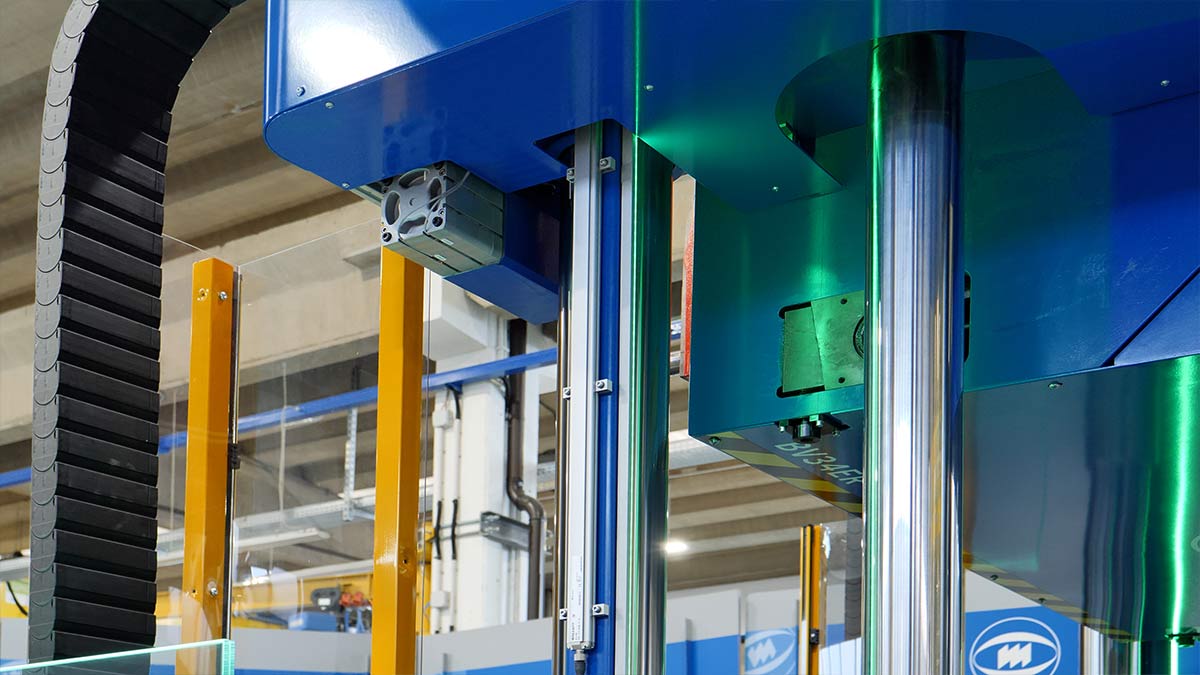
Structure
- Press with 4 chrome-plated alloy steel columns, structures made of welded and normalized steel, and a sturdy cast iron baseplate to guarantee high rigidity and
- Press with 4 chrome-plated alloy steel columns, structures made of welded and normalized steel, and a sturdy cast iron baseplate to guarantee high rigidity and bending resistance.
- Basement embedded in a robust arc-welded structure, that is highly rigid and flexion-proof . Very long maintenance-free press ram precision guides, with bronze bushings lubricated for life with teflon coating. They guarantee high rotation stability and ram repeatability precision
- 4 hydraulic cylinders for the upper plate actuation guarantee an optimal distribution of surface pressure.
- Easy clamping force setting, by means of the touch panel.
- Room-saving arrangement of the hydraulic power unit with considerable noise reduction in press upper part.
- The hydraulic power unit can be easily and safely reached by means of a specific ladder.

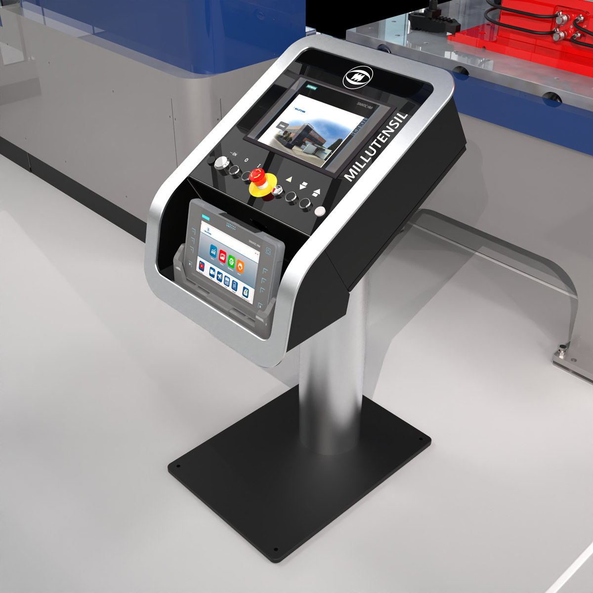
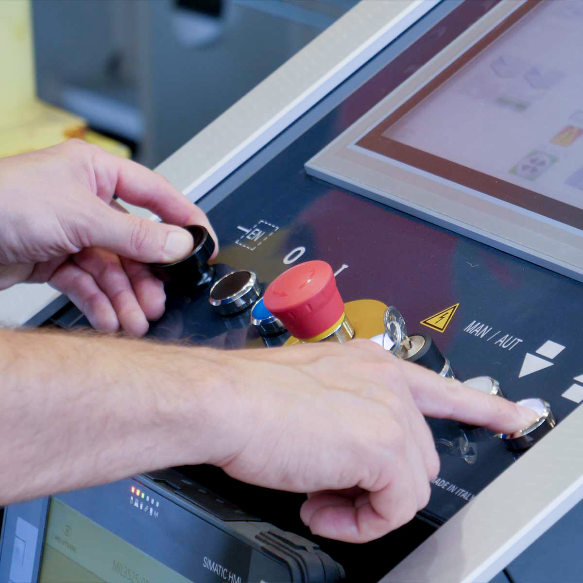
CONTROL PANEL
Siemens S7-1500 control easy to program and use
Pushbutton station equipped with modern Siemens TP1200 MULTIPANEL TOUCH PANEL.
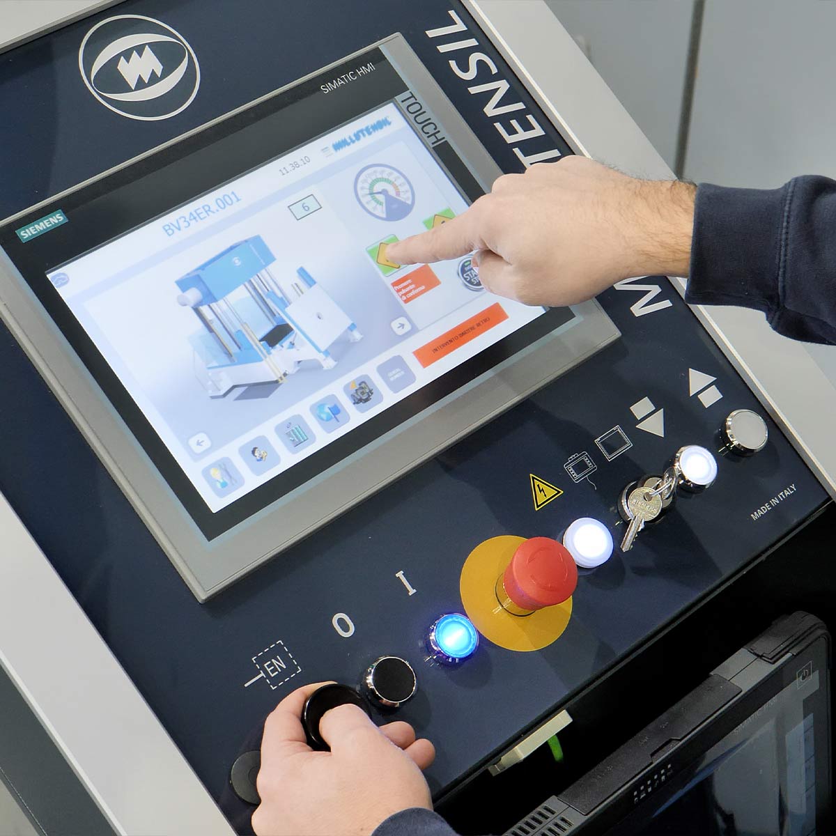
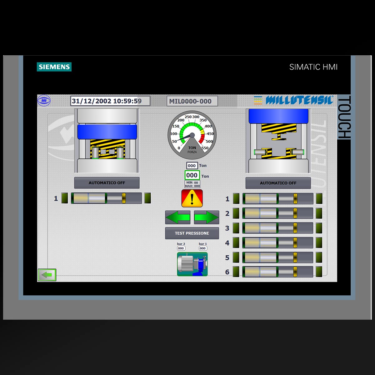
The pulpit station is equipped with a touch panel with a user-friendly graphics to simplify the use of the spotting press. All working movements and functions are graphically shown on the display.
Two-hands command.
Due to security reasons, some functions can be activated only through traditional buttons (i.e. downstroke must be carried out with two-hands, in compliance with EU-UL-CSA safety legislation).
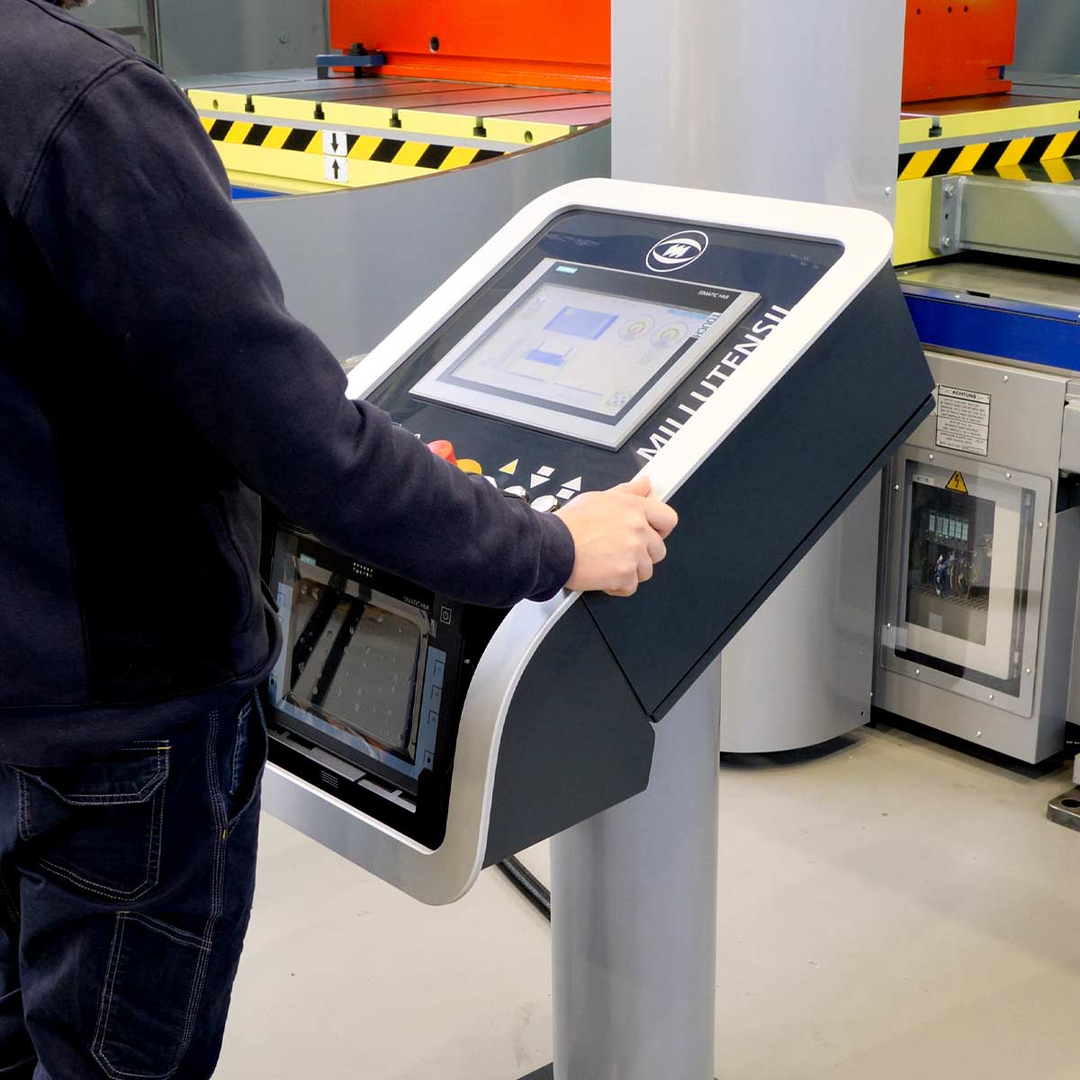
Uncluttered, clear and ergonomic, the panel offers many advantages as well as vast flexibility in customizing features, including command of the auxiliary cylinders.
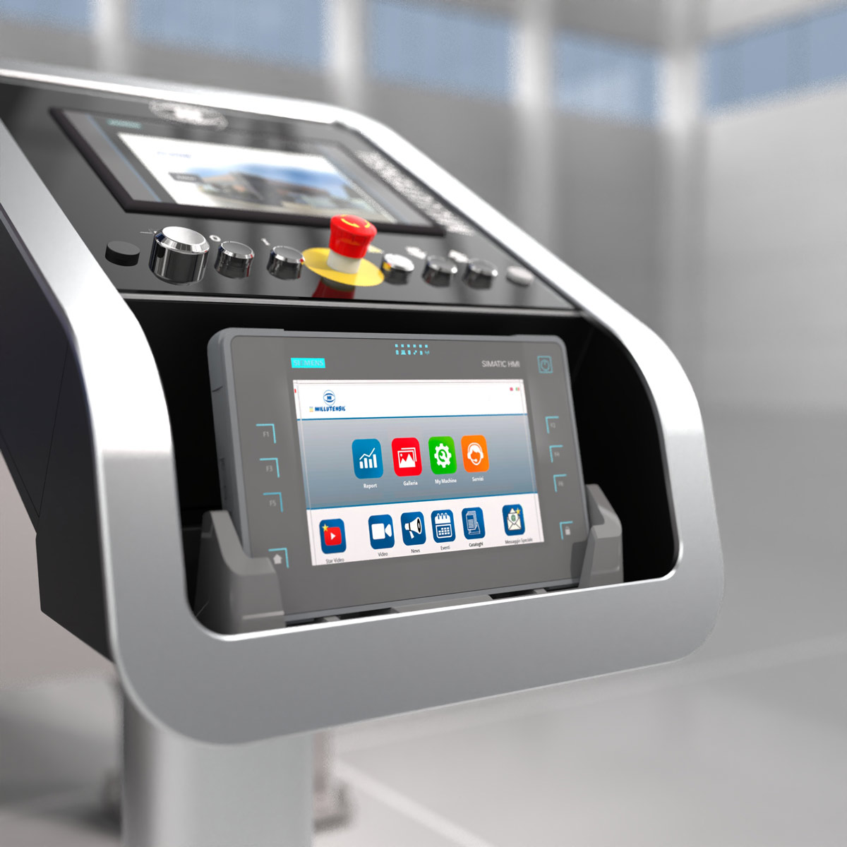
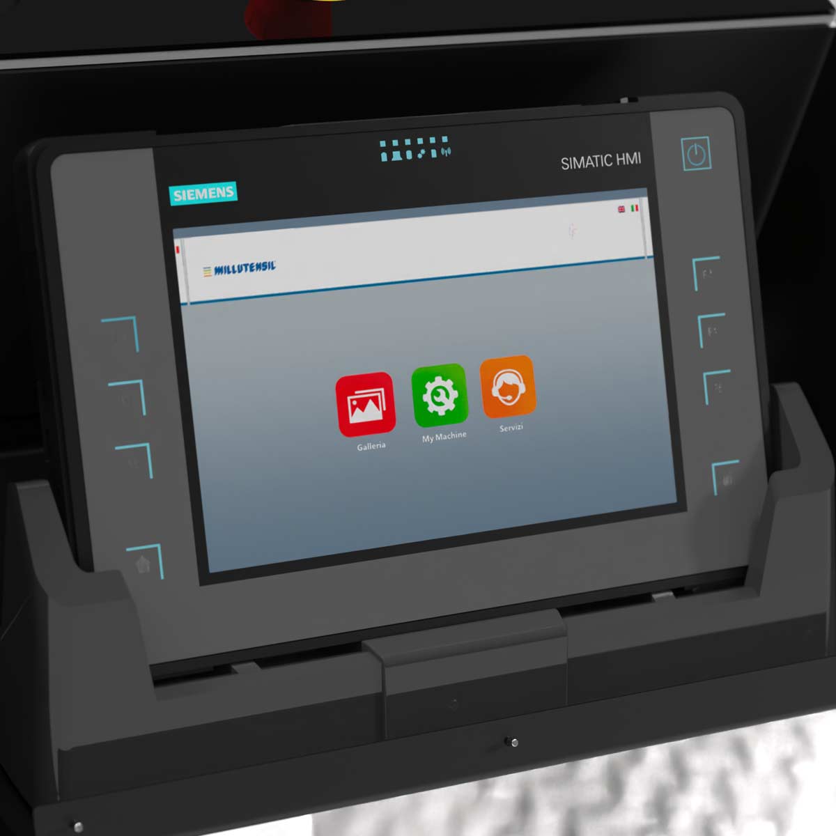
In the pulpit station a new Siemens multi-touch ITP 1000 can be embedded (OPTIONAL).
This new Siemens multi-touch ITP 1000 is supported by a dedicated app called MyMILL© App, that has been developed by Millutensil as a result of the ongoing cooperation between Millutensil and their customers.
KTP400F MOBILE PANEL
In the frontal side of the press, on the platform it is placed a KTP400F Siemens Mobile panel, thanks to which the operator can activate the spotting press without going back to the main mobile panel station. As result adjusting procedures are burden-free.

speed control and setting
The upper plate CLOSURE/OPENING speeds can change automatically thanks to a particular system developed by Millutensil and defined in LEVELS (L1, L2, L3).
The setting of levels (L1, L2, L3) considerably facilitates adjusting operations.
The advantages are:
- maximum repeatability and safety of movements;
- reduction of the risk of accidental impacts.
After fixing the mould, the operator can set, as he deems fit, three different levels according to which the press will automatically apply the corresponding speed changes (L1, L2, L3).
These levels will remain stored can be applied during all opening and closing operations.
The maximum pressure set will be reached in L1 only, when the mould is completely closed.
Operator panel for the setting of levels:
Thanks to this modern system, it is possible to set several speeds (fast during the approaching phase, medium during the working phase and slow during the final mould closing phase).


OPTIONAL VERSIONS

OPTION -R
Lower plate tilting by 75° or 90°
Thanks to 2 hydraulic cylinders, the lower plate can be tilted up to 75° or 90°, on the short back side, to operate on the mould at an ergonomically better position.
Tilting movements (and automatic locking) are controlled by the touch panel.
The plate can be placed at any angle, giving the operator optimal access to the mould, with no need to bend, maximum comfort and safety.

OPTION -G
Extensible plate with integrated 0-180° or 0-90°-120°-180°-240°-270° rotating table formulti-component moulds.
The integrated rotating table in the press’ lower plate has been designed to facilitate themulti-component mould adjustment. Time and cost savings are guaranteed, as moulds do not need to be manually rotated in order to be tested, which is very time consuming.
Furthermore, there is a significant ergonomic gain as the mould can be placed in many different angles, so that the operator who can position the lower half-mould in an optimal and comfortable position to carry out adjusting.
The rotating function is comfortably performed from the touch panel.Press plate rotation is possible either in the 0°-180° or in the 0°90°-120°-180°-240°-270° positions.

OPTION -RG
Extensible plate tilting by 75° or 90° with integrated 0-180° or 0°-90°-120°-180°-240°270° rotating table.
The combination of the optional extensible plate 75° or 90° tilting devices with the integrated rotating table (0°-180 or 0°-90°-120°-240°-270°) guarantees an even higher operator’s ergonomics.
These combined devices make the spotting of multi-component and/or multi-colour moulds even easier.
EQUIPMENTS FOR THE PRESS
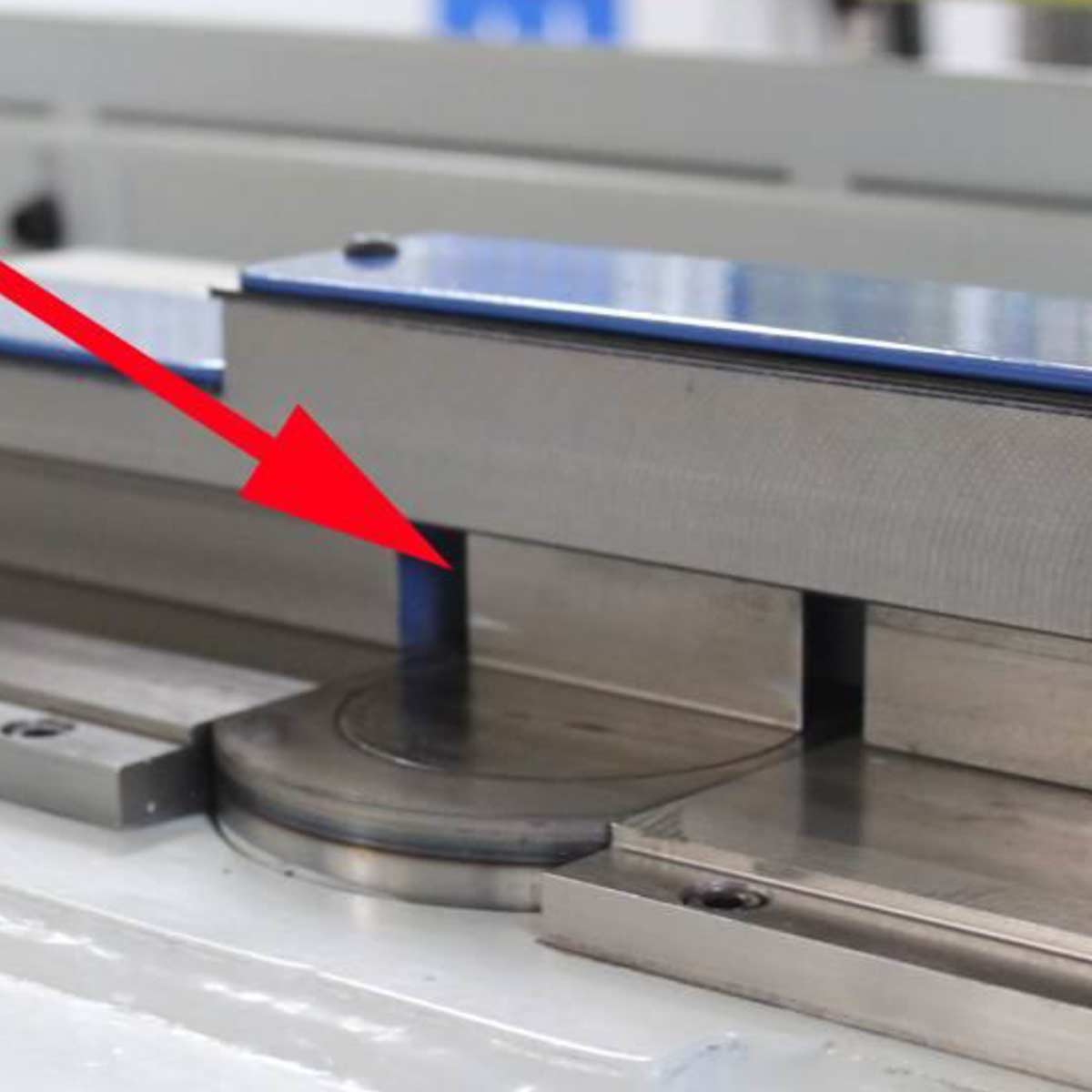
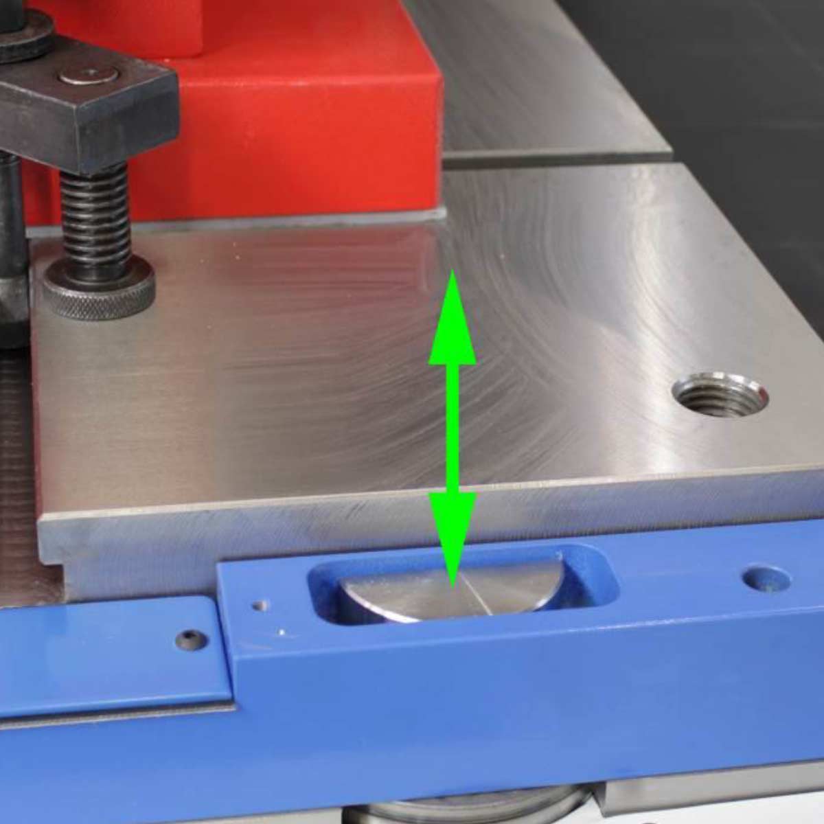
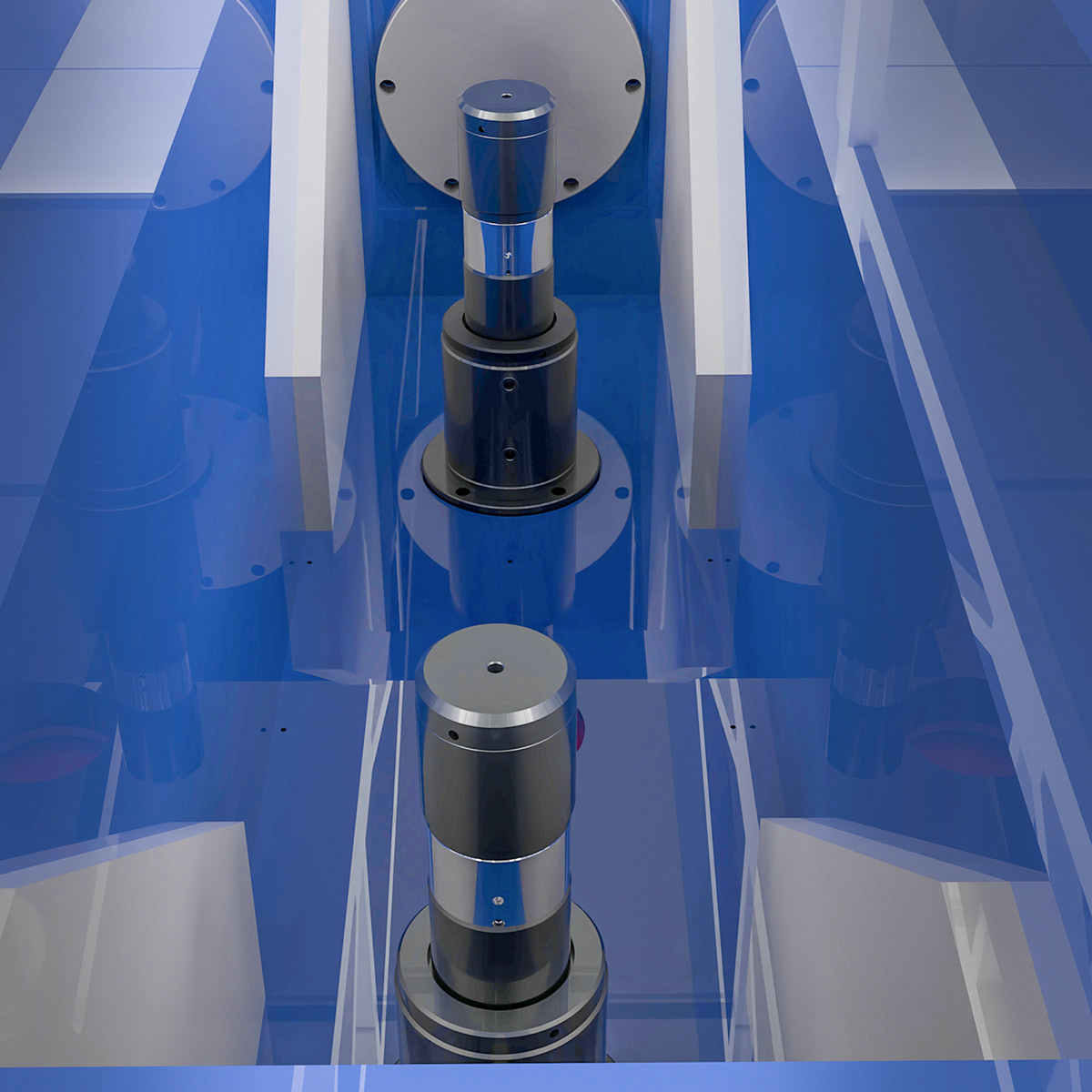
parallelism control system of platens
Electronic upper plate parallelism anti-unbalance safety device, protection of press and moulds.
The upper plate up/down stroke is based on a fully electronic management of the main hydraulic system, which through special proportional servo-valves controls and manages, with maximum accuracy, the oil flow generating the parallel movement of the 2 up/down stroke cylinders.
The control system includes measurement devices (Balluff absolute linear Encoder with magnetic codification), which continuously check the press upper plate position and parallelism compared to the lower plate, and which are located on the sides outside the upper plate, where columns are.
The value is dynamically displayed on the touch panel for the entire stroke.
If the preset limit parameters are exceeded, the ram closing movement is immediately disabled and the parallelism condition is automatically restored by means of the up stroke function. Parameters can be exceeded for example because of slides or hydraulic cylinders not retracted, or tools forgot in the mould (scrapers, grinders, slip gauges, hammers etc.).
In addition to parallelism control, the entire functioning of our solution relies on the accuracy of the lower plate block thanks to hydraulic half cylinders that precisely fix the entire bottom plate allowing a perfect alignment of the two halves of the mold.
Thanks to this system, both press and moulds are protected from potential damages.
Only high-end mold spotting presses are equipped with this system.

SAFETY
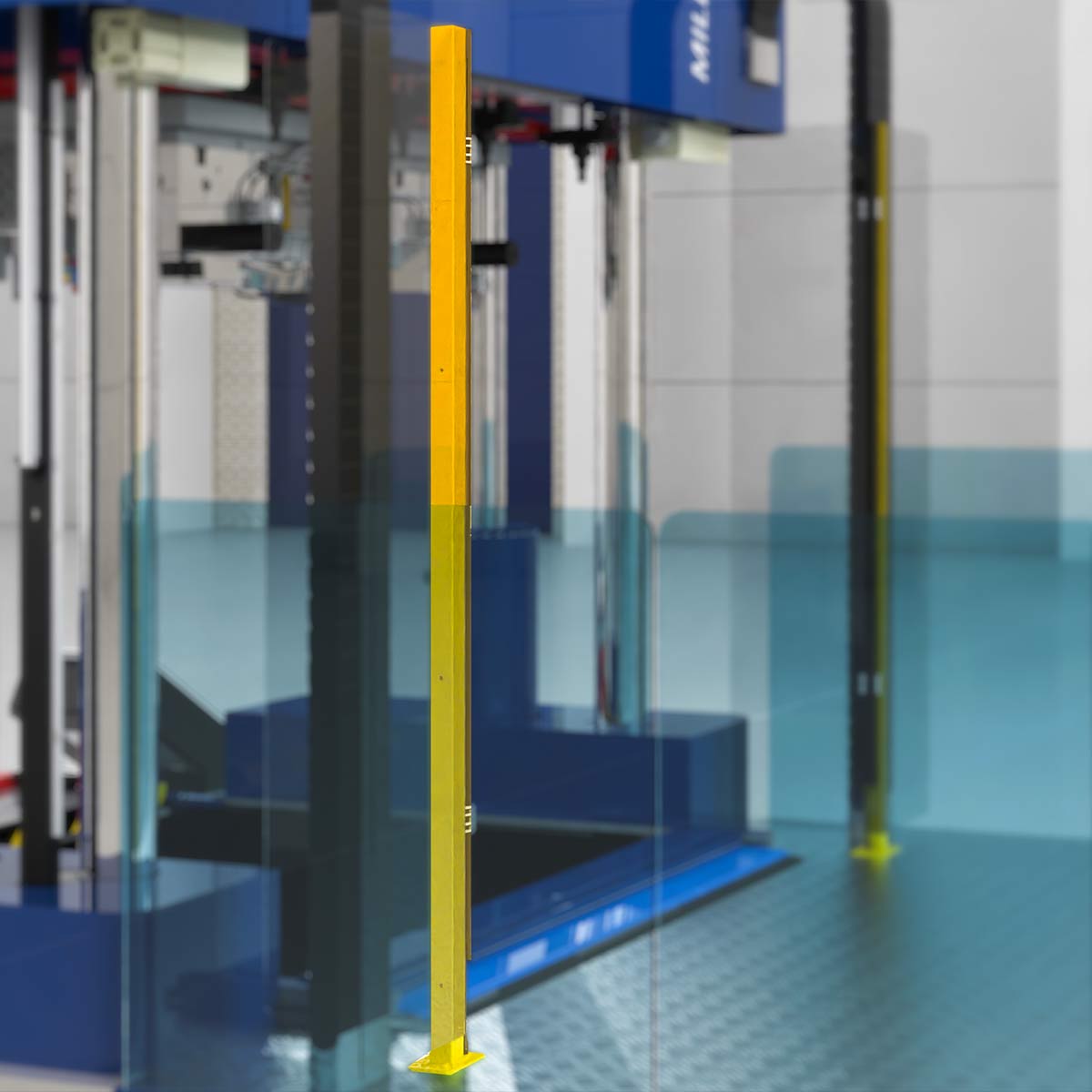
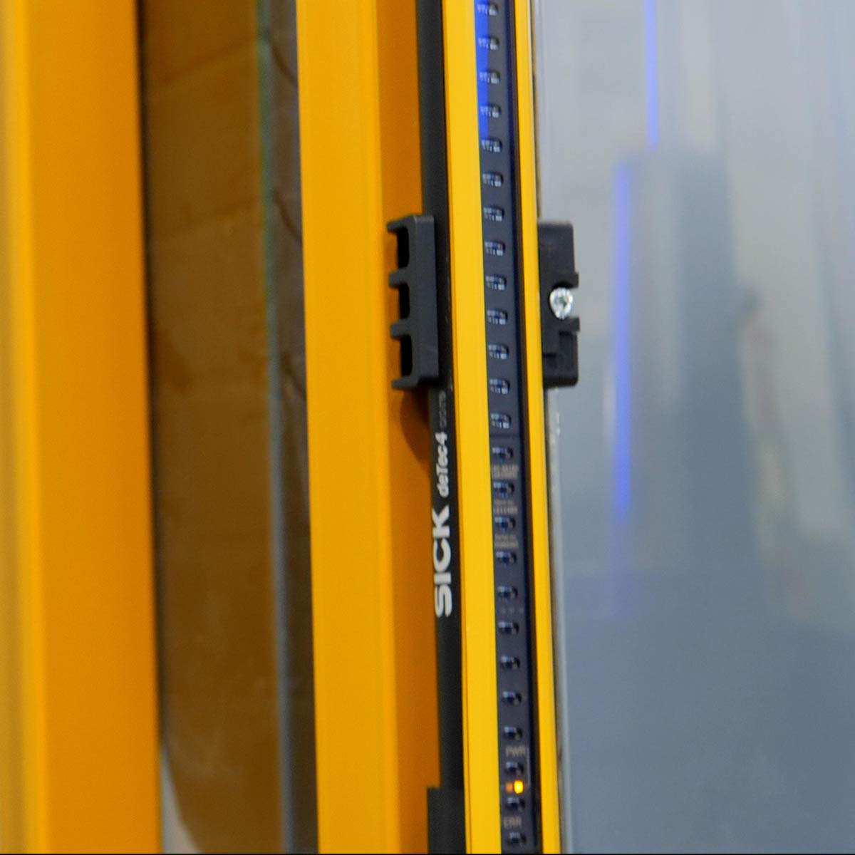
LIGHT CURTAINS: ACCIDENT-PREVENTION PROTECTION DEVICES
The spotting press is equipped with special safety devices made of optics immaterial barriers operated by a specific safety module controlled from the PLC. They are located in the rear area and on the opposite side to the extensible plate.
They guarantee maximum safety for areas partially out of sight of the operator.
FRONTAL PLATFORM
In its frontal side, the spotting press is equipped with a platform. A ladder leads to the platform, whose perimeter is equipped with a glass parapet to guarantee the maximum visibility to the spotting press.
During the installation, thanks to the modular system, it is possible to place the ladder in the most convenient access position to the operator.
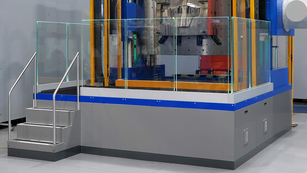
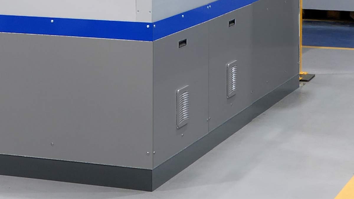
ELECTRICAL CABINET
The electrical panel of MILLUTENSIL presses is located in a dedicated cabinet located in the press under the platform.
All electrical boards and cards, supplied mainly by SIEMENS, are safe in compliance with CE, UL, CSA standards.
green mode
Use of the gravity principle during the entire down stroke.
By means of a special low-pressure circuit, oil is sucked from the tank. This allows a higher speed, without heating the oil, with a definitively low energy consumption.
After 100 seconds out of service, the hydraulic unit turns off in order to save energy. By pressing the specific push-button, the group is activated and hydraulic pressure is immediately restored.
Energy-efficient and low-consumption LED lamps for the optimal lighting of the working area.

OPTIONAL EQUIPMENTS FOR THE MOULDS
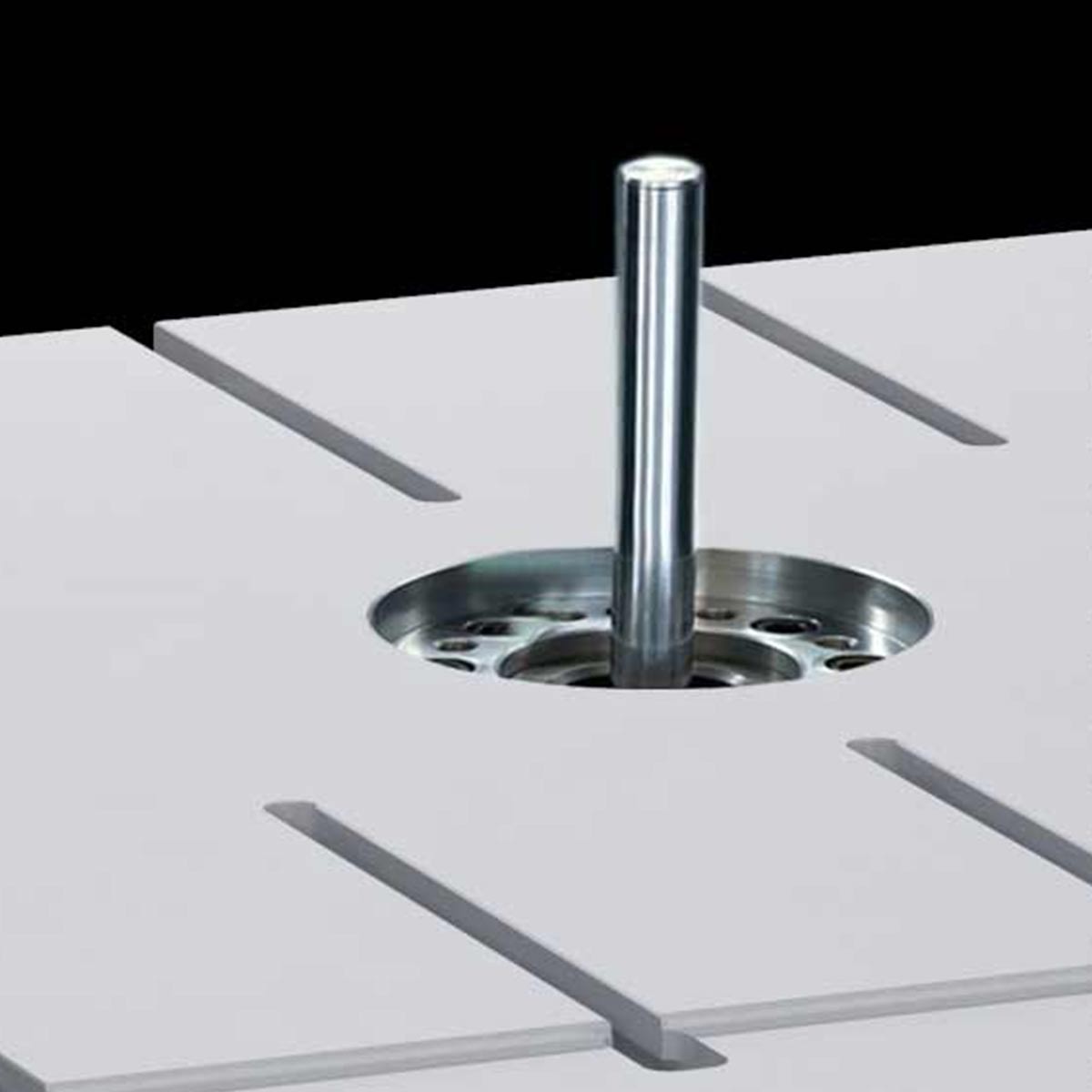
Hydraulic ejection unit
Hydraulic ejector cylinder in the lower plate (option)
The ejection unit initiates the movement of the ejection pins of dies and moulds for plastic materials and die casting.
This utility is made up of a hydraulic cylinder located in the middle of the press basement.
It allows to check and test some important mould functions in a very short time.
The pressure / thrust force is set by means of the il touch panel. The operating pressure depends directly on the line pressure. The advantage is the sensitive test of the mould ejection systems.

ENERGY ACCUMULATOR
Patented single shot energy accumulator
This operation sets up dies and moulds for plastic materials, rubber and die casting.
It is a hydro-mechanical device that should be fixed to the upper plate of the press. It works to strike a shot on the closed mould, in order to better gauge the adjustment between the two mould halves (matrix and punch).
The dynamic action of this device is independent from the press clamping movement. As a consequence, the dynamic action of the energy accumulator will be coupled with the press clamping force.
Automatic special wax injection unit
Option available on MIL 122/123, MIL 142/143, MIL 162/163, MIL 202/203
It provides a way to inject special wax at a low pressure into the mould cavity.
In this way, mould makers can check dimensions and thicknesses of pre-production mouldings (even the thinnest flash) to ensure the correct filling. The wax injection unit includes: wax container with electric heating, pneumatic action with air pressure control and temperature control of the chamber to attain constant wax fluidity.

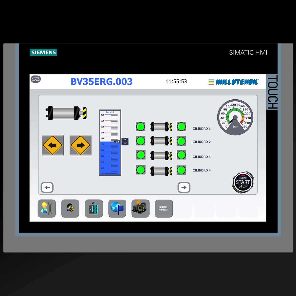
HYDRAULIC AUXILIARY CYLINDER CONTROL UNIT (MAX. 2+2)
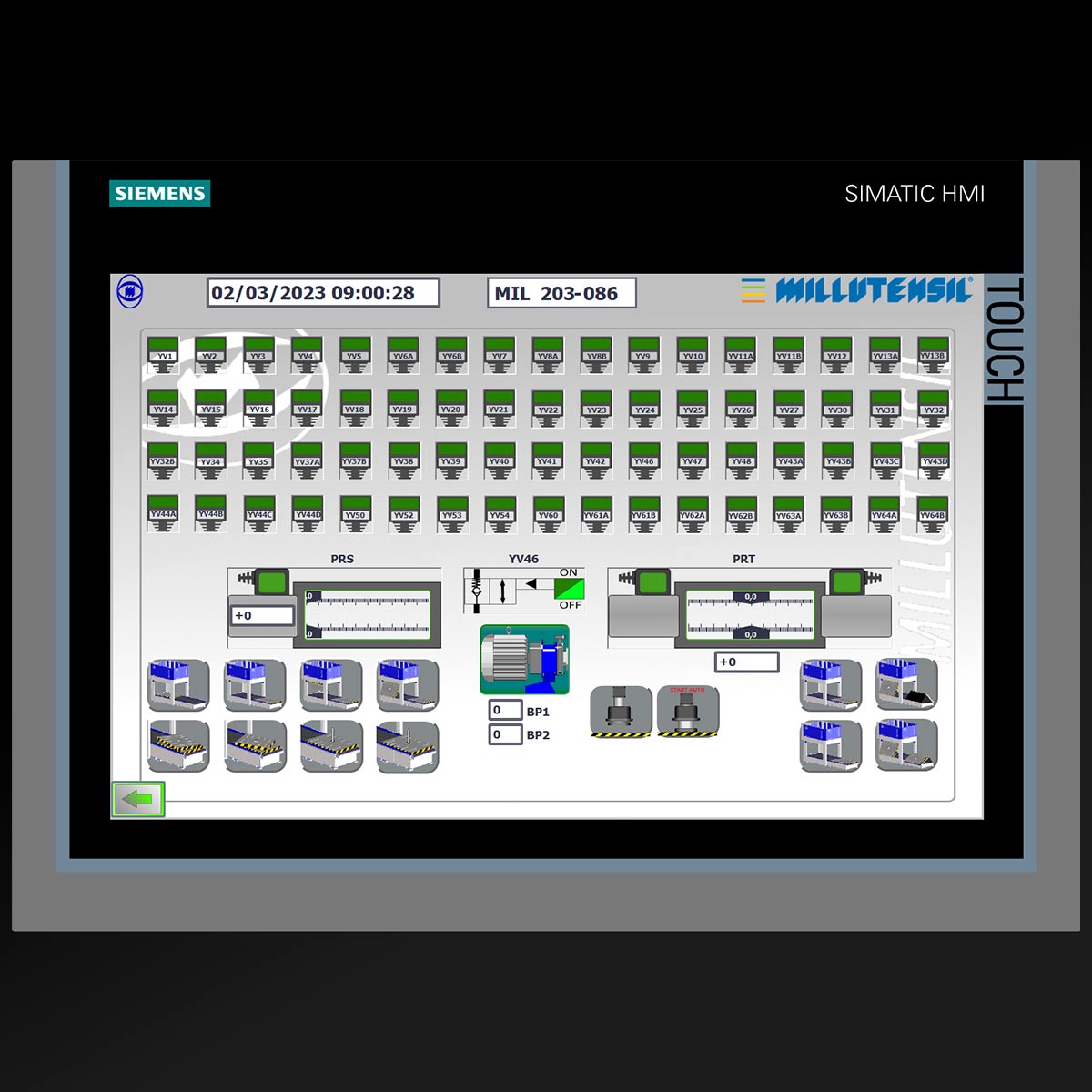
The trial on slide’ and hydraulic cylinders’ movement is wholly integrated in the press. Through the touch panel it is possible to manage 2 pairs of hydraulic cylinders (2 inputs and 2 outputs), either individually or synchronously.
The operating pressure is variable, and it is set always on the touch panel. The hydraulic line connection is made using quick couplers and flexible hoses.
Upon customer’s request, it is possible to configure the mould’s marks with the spotting press in order to test the correct functioning of the sensors and of the hydraulic cylinders.

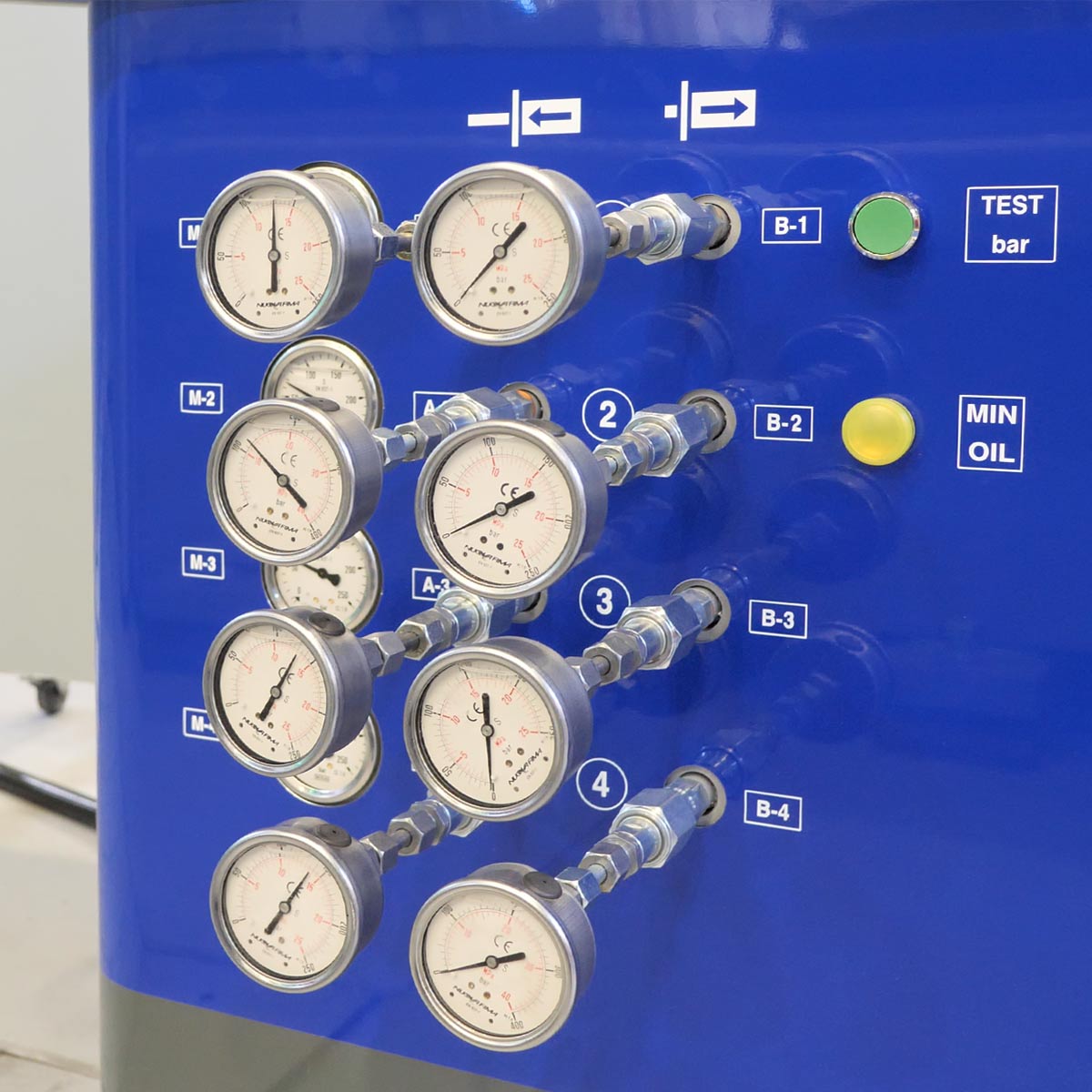
Hydraulic power unit
Separate hydraulic power unit on trolley with connections for hydraulic cylinders (4+4) (option)
A separate and standalone hydraulic power unit on trolley has been designed, in order to test the movements of slides and hydraulic cylinders. This trolley is equipped with a tank, and it is directly connected to the press control panel, with which it is possible to settle up to 4 pairs of hydraulic cylinders (4 inputs and 4 outputs), either individually or synchronously. Each connection pair is equipped with a standalone pressure regulator and an analogue pressure gauge.
The trolley can be provided in a completely stand-alone version with its own dedicated control panel, so that it can be used not only with the spotting press.
Upon the customer’s request, it is possible to configure the marks of the moulds with the spotting press, in order to test the correct functioning of the sensors and of the hydraulic cylinders. We can supply special cycles for the movement of slides/hydraulic cylinders.
The standard trolley is equipped with a pump with a delivery of 8 Liters/min. and a 2.2 kW engine. A customized trolley version is characterized by a pump with a delivery of 40 liters/min. and 11/15 kW engine. A special version for operation with water-glycol mix is also available.


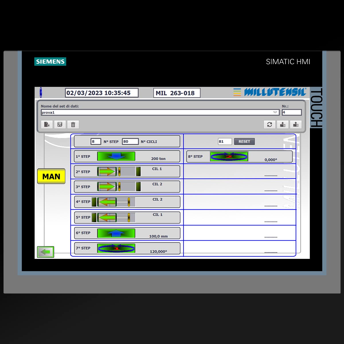
PRODUCTION SIMULATION
Thanks to its experience, MILLUTENSIL has developed FUNCTIONAL TESTS, in order to INCREASE the machine productivity. (option)
Example:
- ENABLING the mould/auxiliary cilinders / sliding beds for a few hours
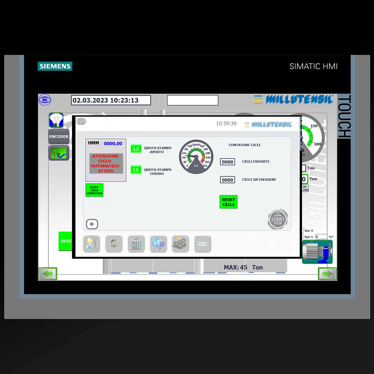
- LAPPING CYCLES
- AUTOMATIC CYCLES
TECHNICAL ASSISTANCE
Diagnostic system
Integrated diagnostic system
MILLUTENSIL die & mould spotting presses are equipped with a specific and exclusive diagnostic program. Any failures occurred during operations is displayed on the control display, where the affected point is indicated. As a consequence, the machine downtime is minimized.
Main advantages:
- Minimization of down time,
- Quick and easy troubleshooting,
- Considerable service costs reduction, especially after the warranty period.
E-Won modem
MIL-Series spotting presses are equipped with a E-Won modem, so that our Millutensil technicians can remotely operate on the spotting press to fix it.
The remote assistance can be easily performed thanks to the hotspot of a mobile phone and a password that is provided in case of need.
Wireless mobile panel
Thanks to the tablet Siemens multitouch ITP 1000 (optional) and its MyMILL© App (optional), remote assistance is simplified, since the tablet can be used to initiate the remote assistance call.
Training
For a complete use of the machine, we provide support and training to technicians during installation on site.


TECHNICAL DATA
| Description | BV 32E/ 33E | BV 34E/ 35E | |
| – Size of press plates | mm | 1600 x 1300 | 2000 x 1500 |
| – Max. clamping force | kN | 1200 / 1500 | 1500 / 2000 |
| – Max. opening force | kN | 350 | 500 |
| – Max. load capacity on lower plate
-R version -RG version |
kg | 16000
10000 8000 |
30000
22000 20000 |
| – Max. load capacity on upper plate | kg | 10000 | 15000 |
| – Min. – max. opening between plates
-G / -RG version |
mm | 600 – 1600
400 – 1400 |
700 – 1900
500 – 1700 |
| – Distance between columns | mm | 1800 | 2200 |
| – Upper plate approaching speed | mm/sec | 20 | 20 |
| – Upper plate working speed | mm/sec | 5 | 5 |
| – Power of main motor | kW | 25 | 25 |
| – Machine weight | kg~ | 21000* | 30000* |

Layout BV 32 / BV 33
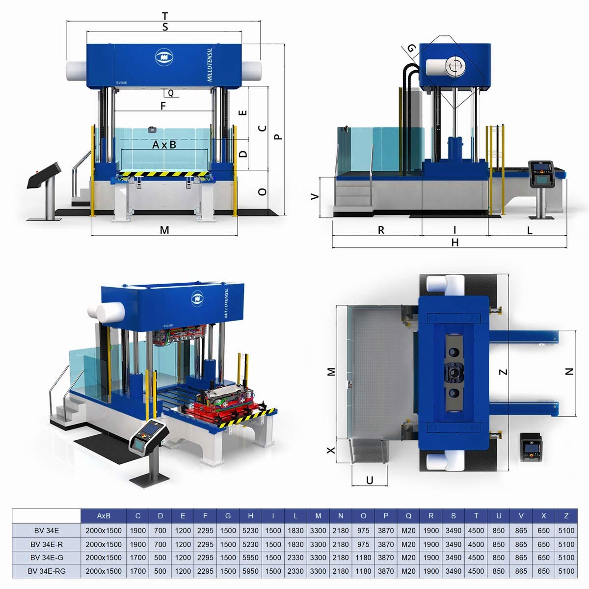
Layout BV 34 / BV 35
Other solutions
BV 25P
The BV 25 P is the smallest and most simplified version of the Millutensil’s spotting presses, without hydraulic electronic and parallelism control.
The control panel of the BV 26 C is equipped with manual function buttons to simplify the use of the spotting press.
Platen dimensions are 770×660 mm.

BV 26C
The BV 26 C is the entry level version of the Millutensil’s spotting presses, without hydraulic electronic and parallelism control.
The control panel of the BV 26 C is equipped with manual function buttons to simplify the use of the spotting press.
Platen dimensions are 980×750 mm.
BV E SERIES
Three models available depending on the platen dimensions, (980×750 mm / 1.200×1.000 mm / 1.500×1.000 mm) with a hydraulic system controlled by electronic servo proportional valves and a control of parallelism through Heidenhain optical lines.
All models are equipped with user-friendly graphics touch control panel.
The E series presses are offered with option -R, -G or -RG version and can also be equipped with all optional accessories.
Our worldwide references
