SPOTTING PRESSES FOR ASSEMBLY, ADJUSTMENT, CHECKING AND REPAIR OF MEDIUM AND LARGE MOULDS AND DIES
The Millutensil MIL series spotting presses is offered in two versions: Classic and Compact. The Classic version is tipically used in plastics and rubbers sectors, while the Compact version is designed for die-casting sectors.
In the Classic version, for large sized molds, we offer the 300 series with table dimensions ranging from 3000 x 2000 to 3500 x 2500 mm.
In the Compact version, for large sized molds, we provide the 3000 series with table dimensions from 2000×3000 mm to 3500×2500 mm.
MIL Classic Series
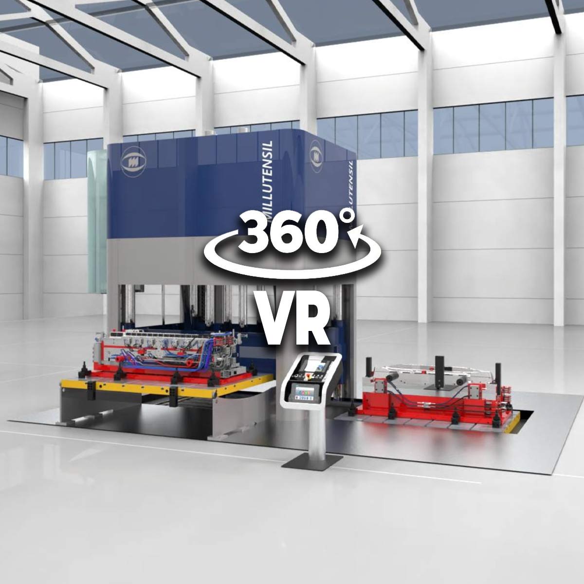
PIT VERSION *suggested model ideal for large sized moulds
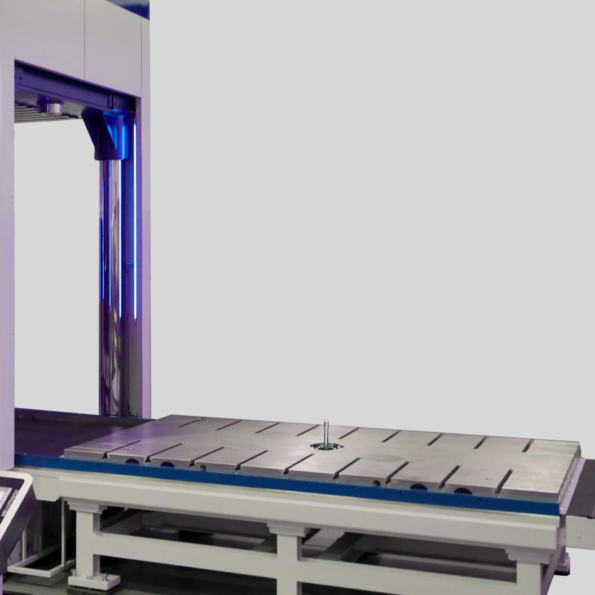
The die & mould spotting presses of the traditional MIL/CLASSIC series feature the extensible plate exit on the side, towards the short side of the distance between columns. They are typically used in the plastics, rubber and die casting sectors.
In this version, the upper plate, can be tilted on the short side from 100° to 180°.
The MIL/CLASSIC series provides great advantages compared to other solutions with long side tilting:
- Better working ergonomics, granting the operator an easy access to any mould part, without the use of platforms;
- Much shorter total press height above ground, which often reduces excess costs for foundations;
- Wide base press structure with greater stability;
- The two mould-halves are located on the same side. In this way, operators have an overview of the whole mould and can work more comfortably.
MIL Compact Series

PIT VERSION
The MIL/COMPACT series die & mould spotting presses are a riveting innovation to optimize adjustments in the die casting sector.
They feature the extensible plate exit on the backside, towards the longest side of the gap between the columns. In this sector moulds are relatively small, but they are often equipped with internal sliding beds that are driven by very long auxiliary cylinders, considerably increasing the total dimensions of the mould overall.
Therefore, the MIL/COMPACT series provides significant benefits:
- Carrying out adjusting operations on a smaller and therefore cheaper press with subsequent reduction of the investment amortization period;
- Possibility to design the plate exit on the backside with special travels.
The significant advantage of the MIL COMPACT series lies in the handling of molds with very long auxiliary cylinders that do not require disassembly, ensuring significant time savings. The passage between the columns of the press on the long side is indeed very spacious.
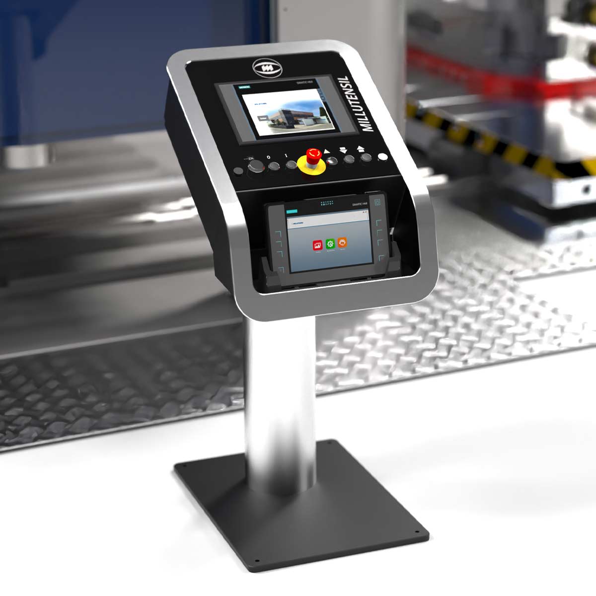
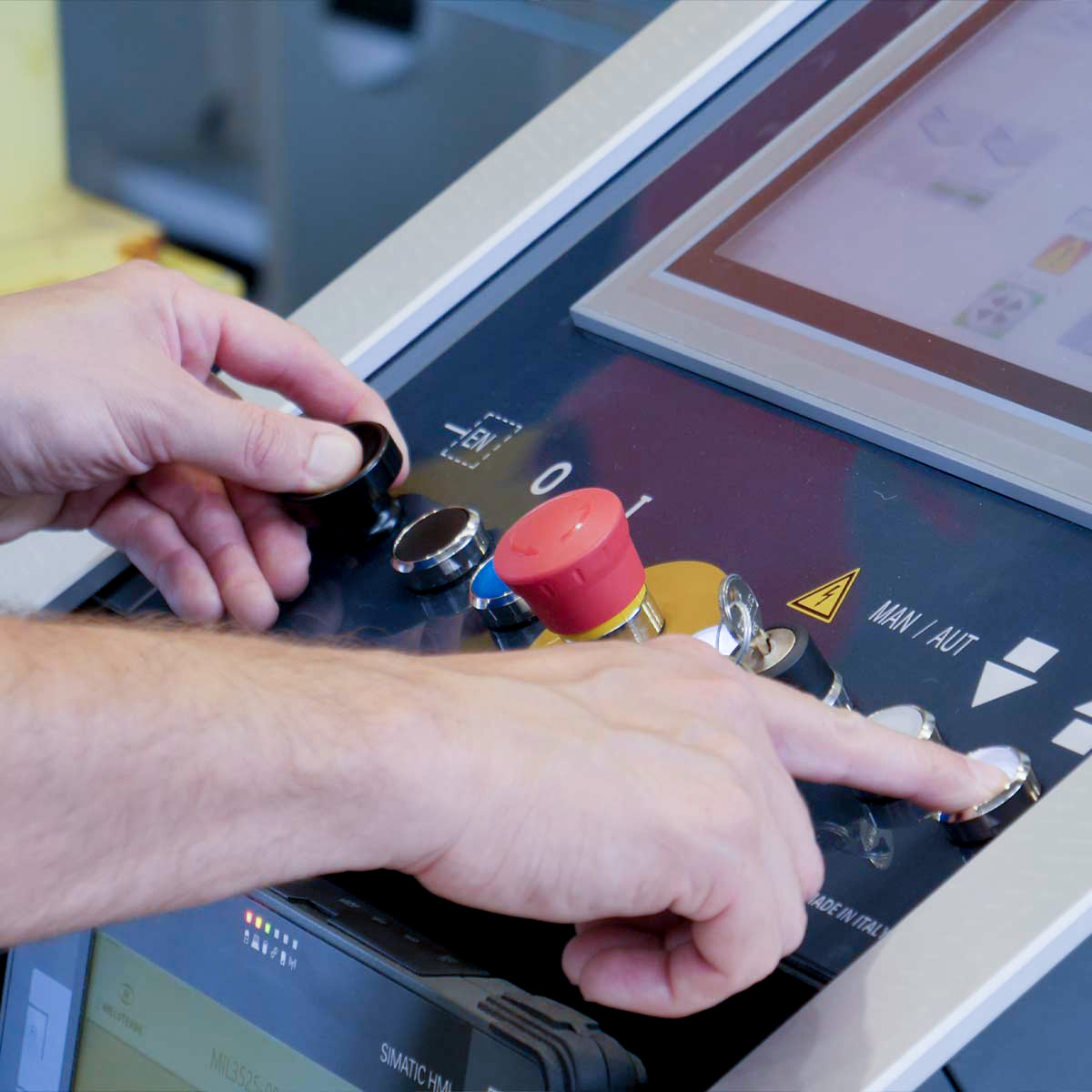
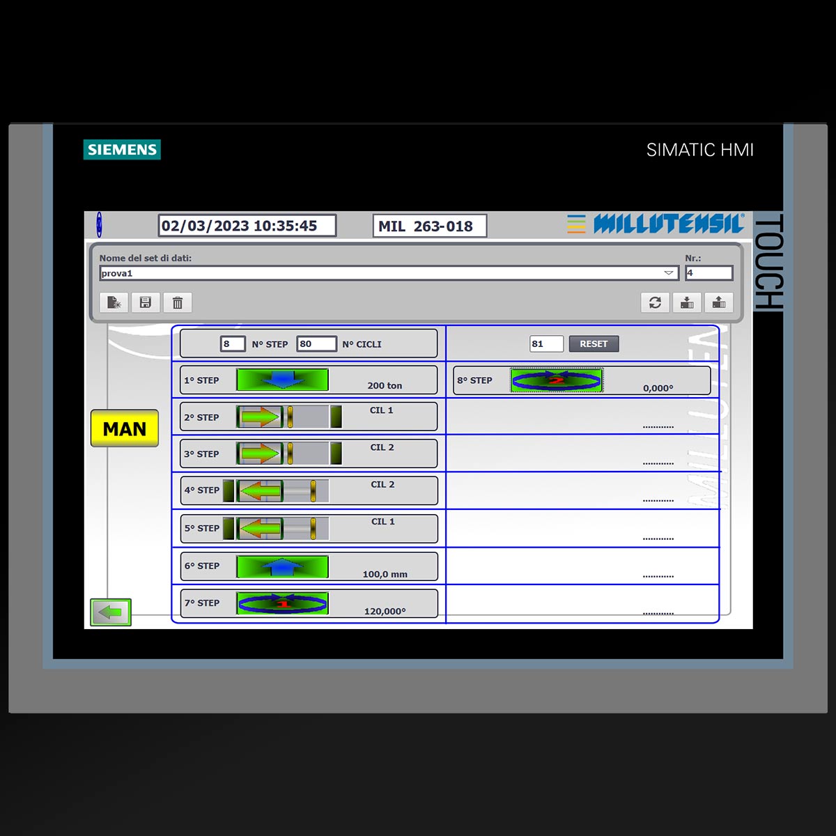
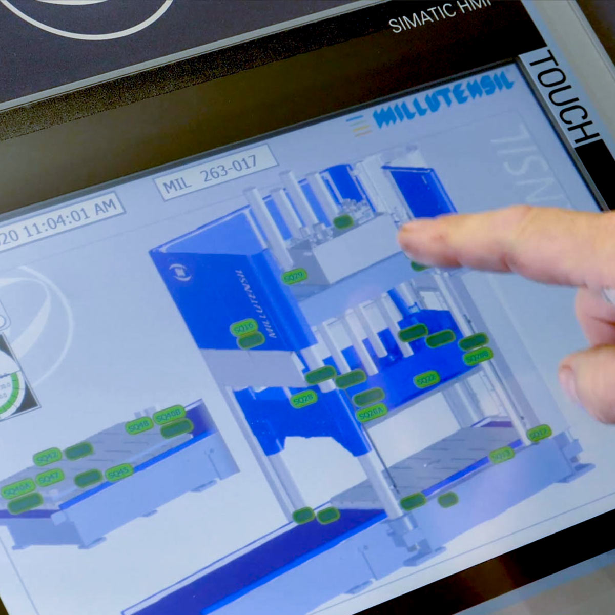
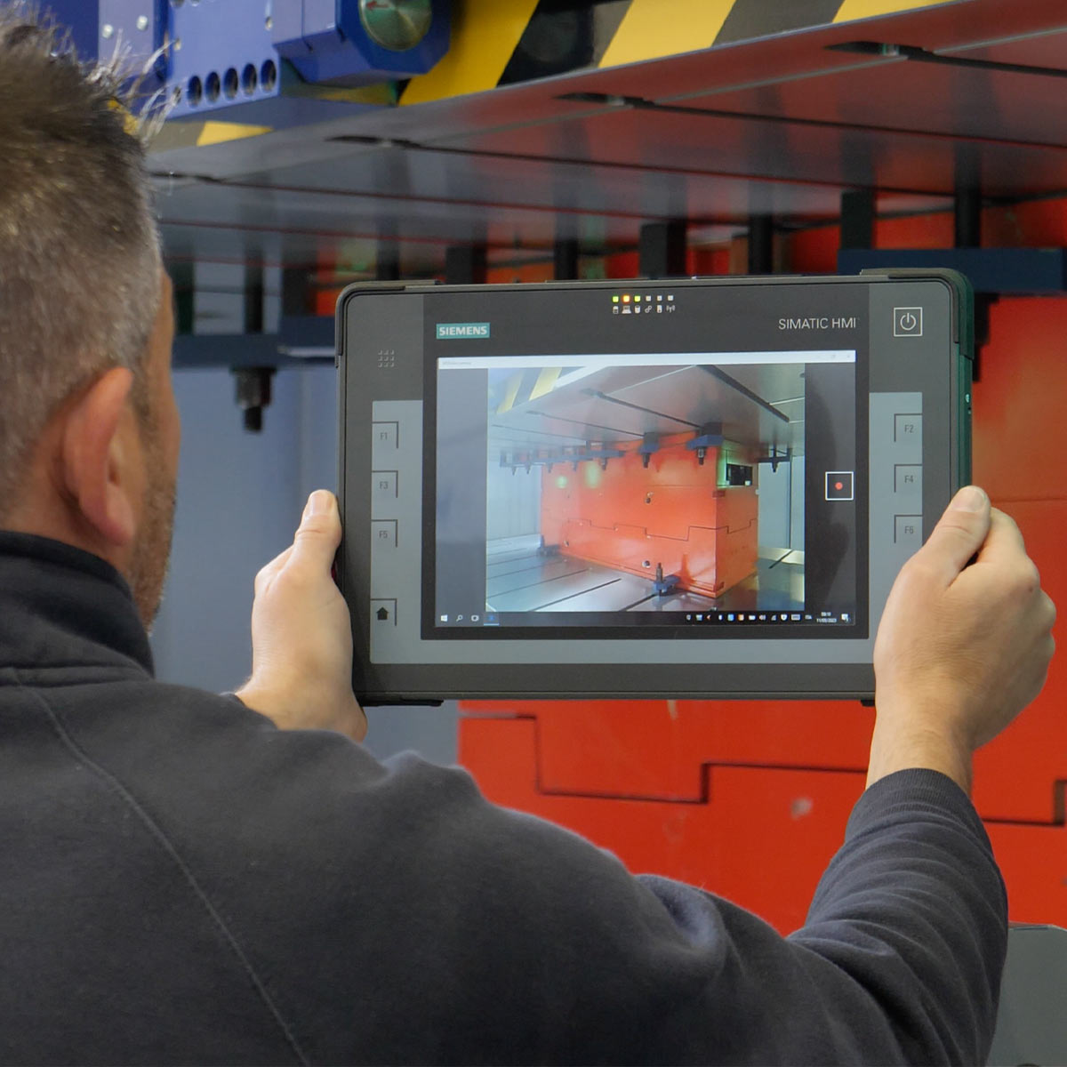
All models are equipped with user-friendly graphics control panel, monitored through Siemens PLC commanded by Touch Panel installed in a pulpit station.
All components are purchased from well-known manufacturers, such as for example: hydraulic system Bosch-Rexroth, Hawe; electrical system Siemens, Schneider Elektrik, Phoenix Contact, Weidmüller. This guarantees a general good functionality of the press, and a quick procurement all over the world.
EC Declaration of Conformity and compliance with safety provisions in accordance with the current EC standards.
PLATENS MOVEMENTS
UPPER PLATE
The press upper plate can be tilted forward up to 100°.
By tilting the press plate, the operator can work at an optimal height, normally standing, without having to use instable ladders, platforms or lifting equipment.
In order to increase comfort and improve access to the press upper plate and to the moulds fastened on it, the press upper plate can be tilted forward up to 180°.

This occurs through the down stroke function with the plate leaning on 2 shaped brackets.
During the first phase, the press upper plate is tilted by up to 100°. After that, with the down stroke movement, the press plate leans and slides on the 2 shaped brackets up to the final position. It is possible to stop in all intermediate positions.
After complete closure, the press plate is automatically centred with high precision and locked by a system driven by hydraulic cylinders.
The use of plate tilting by up to ~ 180° guarantees optimal access and high working comfort in any working position.

LOWER PLATE
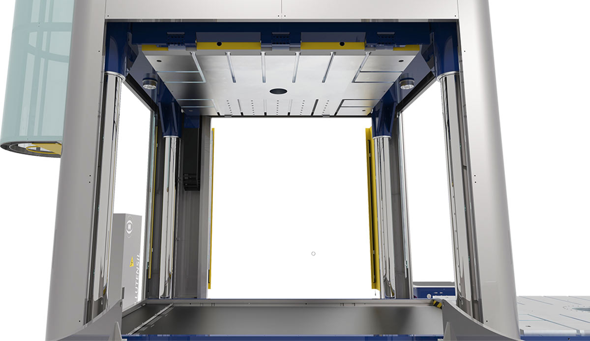
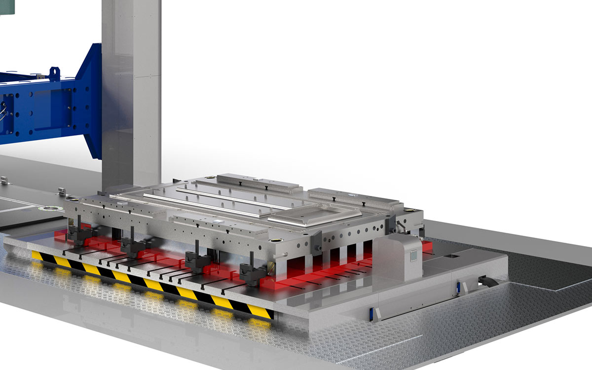
The lower plate is extensible, sliding on the base guided by ball bearings.
In the final position, the plate comes down and is held by means of 6/8 motor cylinders, thus completely leaning on specific ground support bands.
The system guarantees high repeatability accuracy equal to ± 0,04 mm.
It allows to draw the lower part of the die or mould out of the press into an effortless working position
VIDEO
COMMON FEATURES MIL CLASSIC AND MIL COMPACT VERSIONS
HYDRAULICS
The hydraulic system is manufactured with components by the main international companies such as BOSCH, REXROTH, HAWE etc. in order to guarantee:
- high performance
- long operating life
- easiness to find spare parts all over the world
Green mode
Use of the gravity principle during the entire down stroke.
By means of a special low-pressure circuit, oil is sucked from the tank. This allows a higher speed, without heating the oil, with a definitively low energy consumption.
After 100 seconds out of service, the hydraulic unit turns off in order to save energy. By pressing the specific push-button, the group is activated and hydraulic pressure is immediately restored.
Energy-efficient and low-consumption LED lamps for the optimal lighting of the working area.
Hydraulic component layout
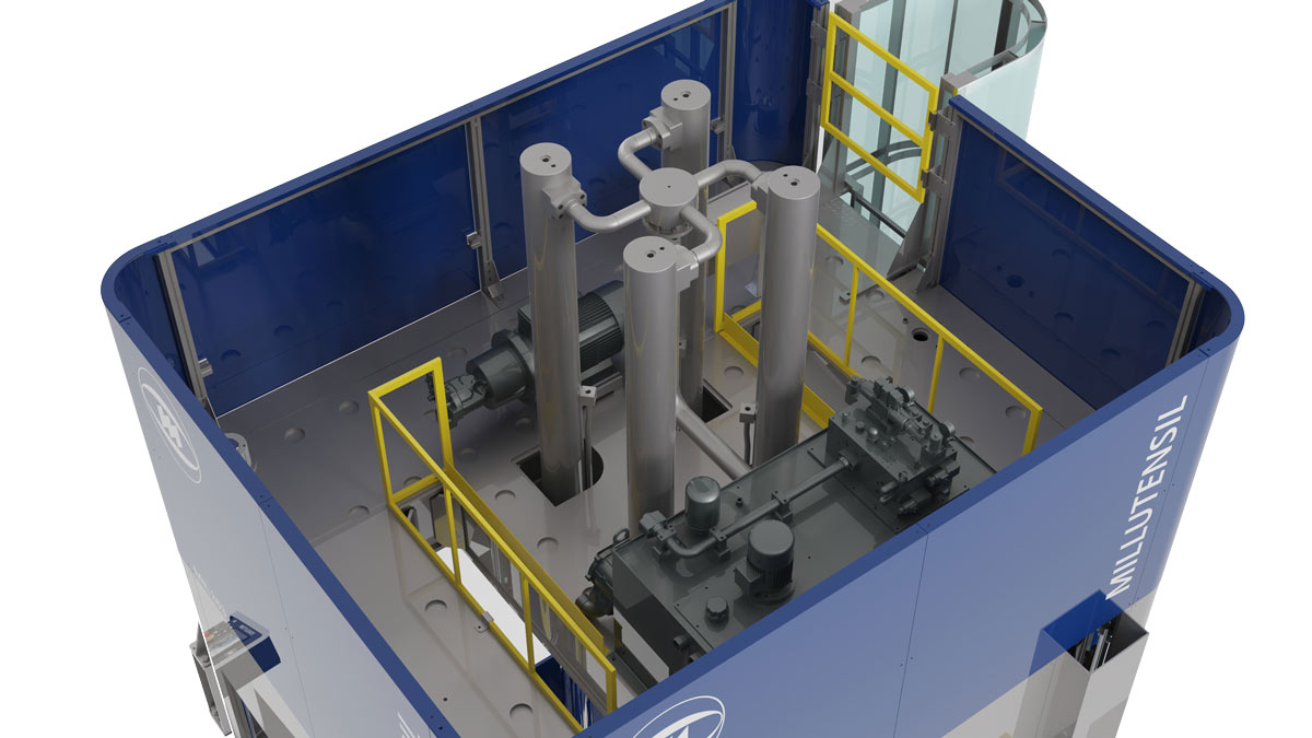
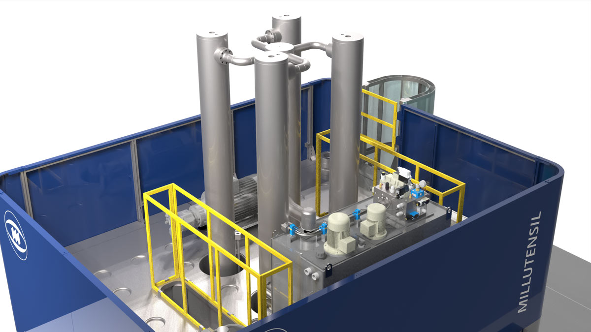
In the entire range of Millutensil die & mould spotting presses, the main hydraulic power unit is placed directly in the press upper part, and can be reached by means of a service ladder. The advantage is that there are no bulky tanks with noisy hydraulic power units located on the ground around the machine. This allows to reduce cable and pipe connections.
Moreover, the extensive press housing considerably facilitates cleaning and routine maintenance.
The upper platform, completely surrounded by specific protection panels, which is a particular design by Millutensil, also guarantees further noise abatement for motor/pump units.
Clamping pressure cylinders
In the MIL series presses, a 4-cylinders system is adopted.
This allows to distribute pressing forces in a more uniform way and on a greater area (with great advantages especially on big presses).
Hydraulic cylinders:
- are equipped with high-efficiency gaskets by the main international brands;
- are manufactured using the best steels;
- are equipped with ground and polished rods;
- are provided with fully chrome-plated and polished stems.
Clamping force is easily adjustable via touch panel.
STRUCTURAL PARTS
Press with 4 chrome-plated alloy steel columns, structures made of welded and normalized steel, to guarantee high rigidity and bending resistance.
Columns and guide bushings
Columns are made of thick chrome-plated and mirror polished high-quality alloy steel.
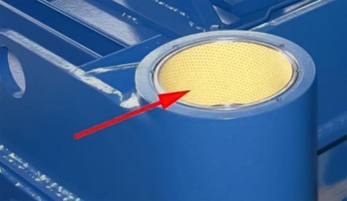
The intermediate structure slides guided by particular completely maintenance-free low-friction bushings.
Press basement design
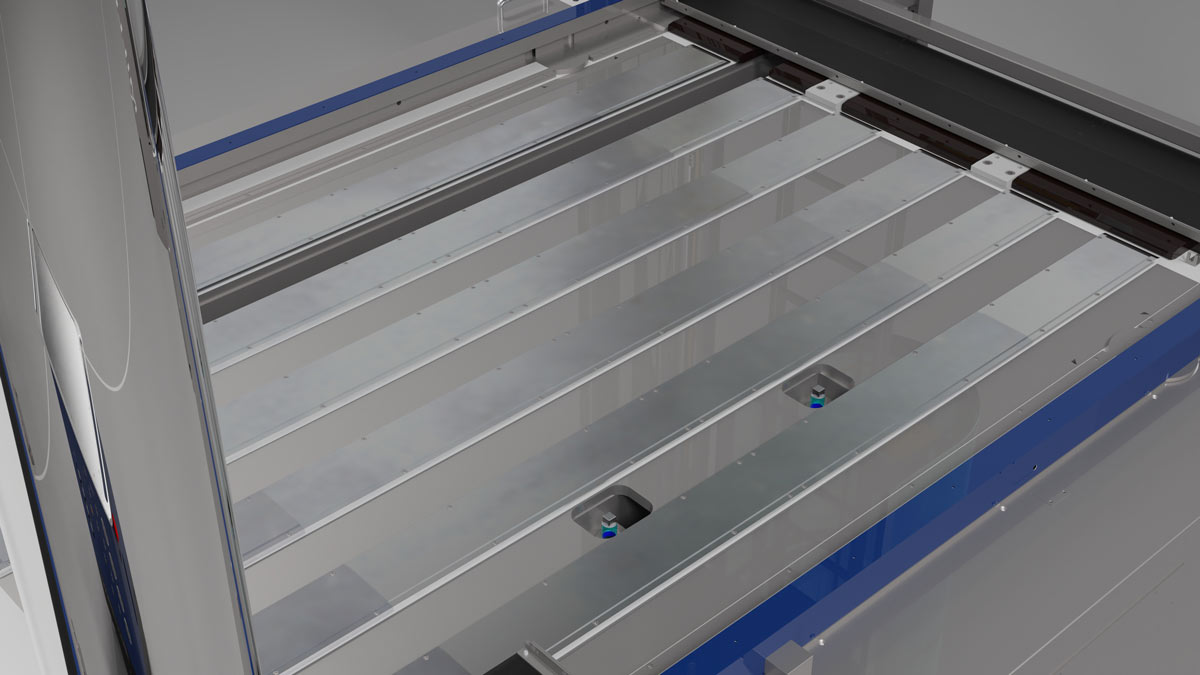
The press basements are equipped with a variable number of ground and screwed support bands according to model.
They perform a support function for the extensible plate after this latter has been positioned.
This solution guarantees accuracy and allows to easily restore geometry, even after many years use.
CONTROL PANEL
Siemens S7-1500 control easy to program and use
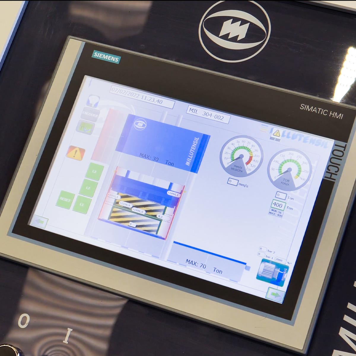
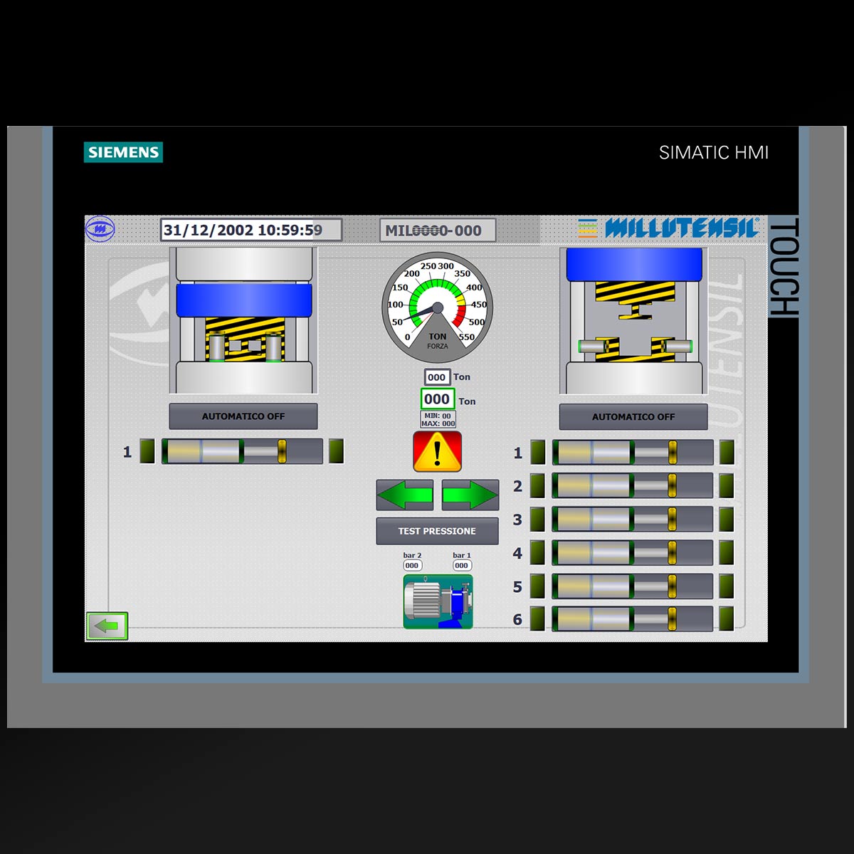
Pushbutton station equipped with modern Siemens TP1200 MULTIPANEL TOUCH PANEL.
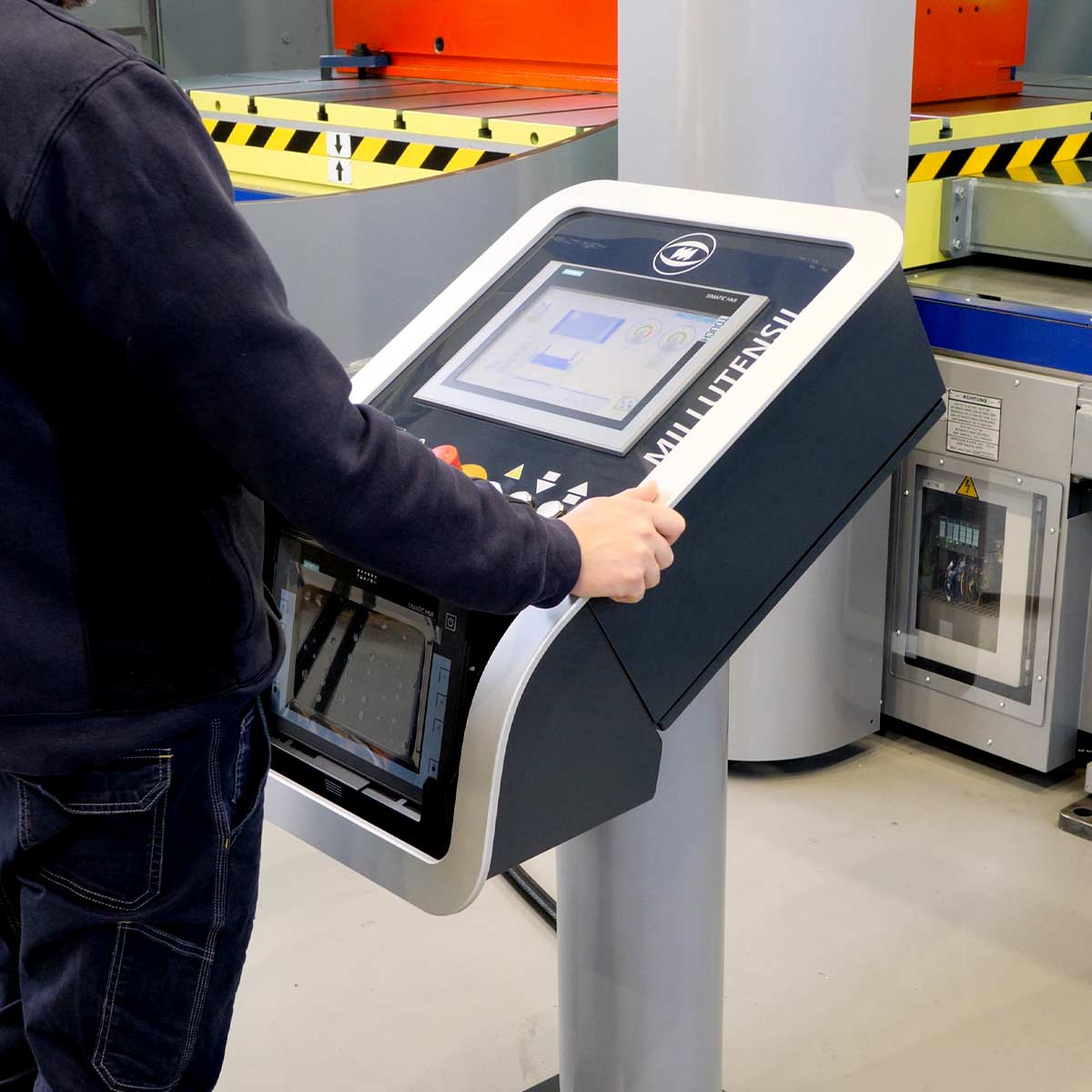
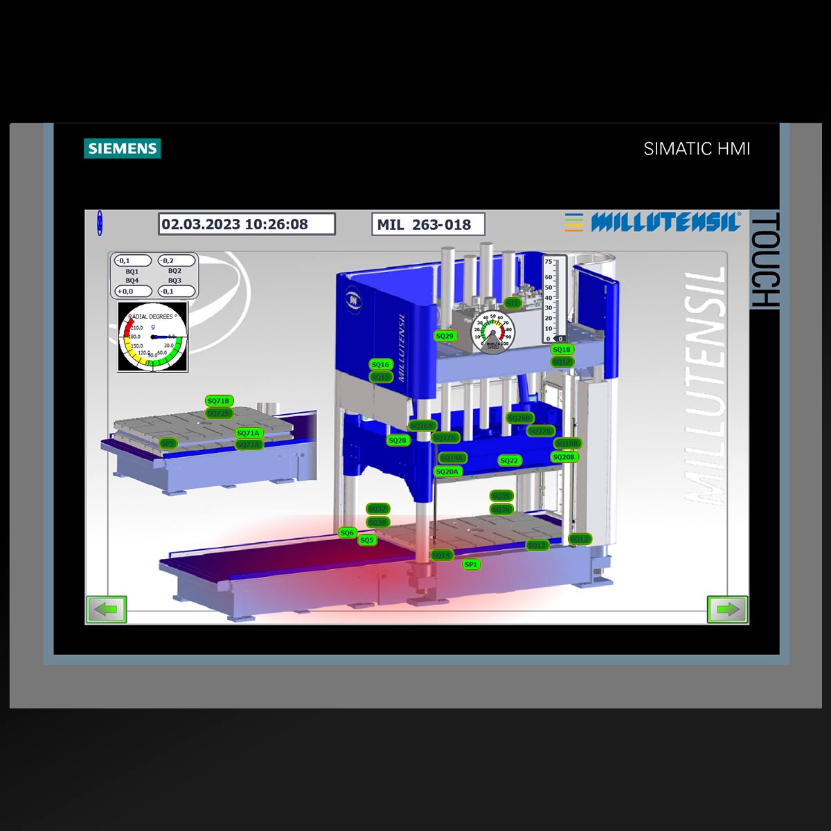
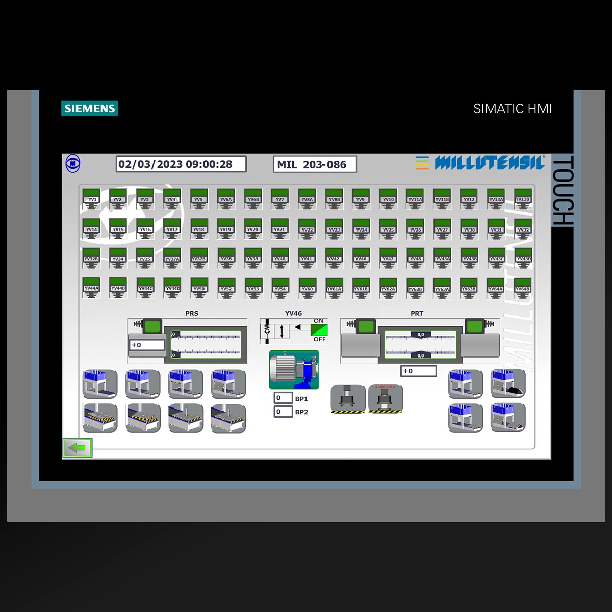
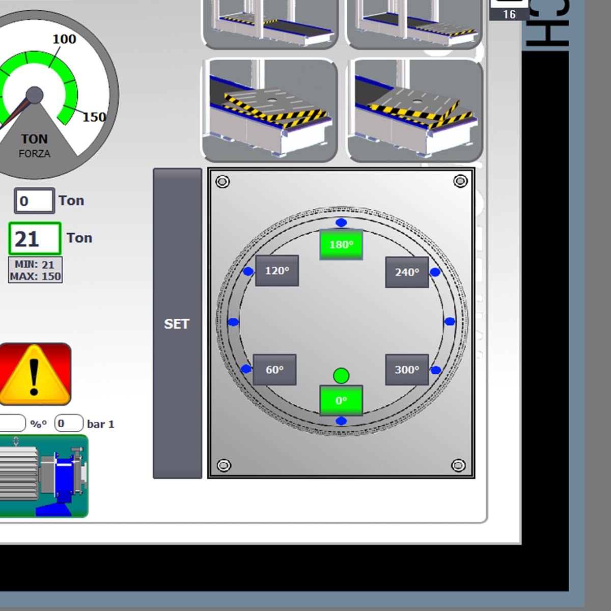
The pulpit station is equipped with a touch panel with a user-friendly graphics to simplify the use of the spotting press. All working movements and functions are graphically shown on the display.
Two-hands command.
Due to security reasons, some functions can be activated only through traditional buttons (i.e. downstroke must be carried out with two-hands, in compliance with EU-UL-CSA safety legislation).
Uncluttered, clear and ergonomic, the panel offers many advantages as well as vast flexibility in customizing features, including command of the auxiliary cylinders.
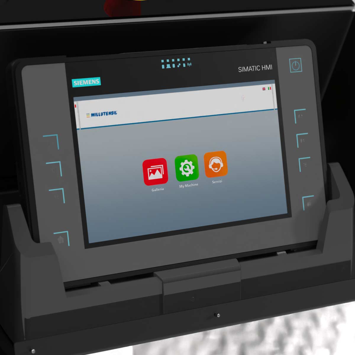
In the pulpit station a new Siemens multi-touch ITP 1000 can be embedded (OPTIONAL).
This new Siemens multi-touch ITP 1000 is supported by a dedicated app called MyMILL© App, that has been developed by Millutensil as a result of the ongoing cooperation between Millutensil and their customers.
speed control and setting
The upper plate CLOSURE/OPENING speeds can change automatically thanks to a particular system developed by Millutensil and defined in LEVELS (L1, L2, L3).
The setting of levels (L1, L2, L3) considerably facilitates adjusting operations.
The advantages are:
- maximum repeatability and safety of movements;
- reduction of the risk of accidental impacts.
After fixing the mould, the operator can set, as he deems fit, three different levels according to which the press will automatically apply the corresponding speed changes (L1, L2, L3).
These levels will remain stored can be applied during all opening and closing operations.
The maximum pressure set will be reached in L1 only, when the mould is completely closed.
Operator panel for the setting of levels:
Thanks to this modern system, it is possible to set several speeds (fast during the approaching phase, medium during the working phase and slow during the final mould closing phase).

EQUIPMENTS FOR THE PRESS
parallelism control system of platens
Electronic upper plate parallelism anti-unbalance safety device, protection of press and moulds.
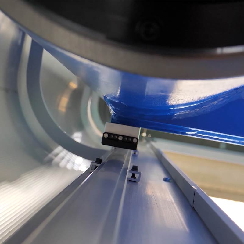
The control system is made of 4 linear magnetic encoders with decimal precision, located on the external corners of the upper plate, near the columns.
They consist of an aluminium profile with an IO-Link language and a magnet for reading the position that runs close to the profile, without touching it.
This device is used to continuously check the position and the parallelism of the upper plate of the press compared to the lower plate.
The values measured are dynamically displayed on the touch panel for the entire stroke.
In addition to parallelism control, the entire functioning of our solution relies on the accuracy of the lower plate block thanks to hydraulic half cylinders that precisely fix the entire bottom plate allowing a perfect alignment of the two halves of the mold.
Thanks to this system, both press and moulds are protected from potential damages.
Only high-end mold spotting presses are equipped with this system.
Roll carpet protection devices
Die & mould spotting presses are equipped with roll carpet protection devices whose particular feature is that they can be walked on.
The design philosophy of Millutensil is aimed at developing solutions that can guarantee the best ergonomics and highest safety for operators.
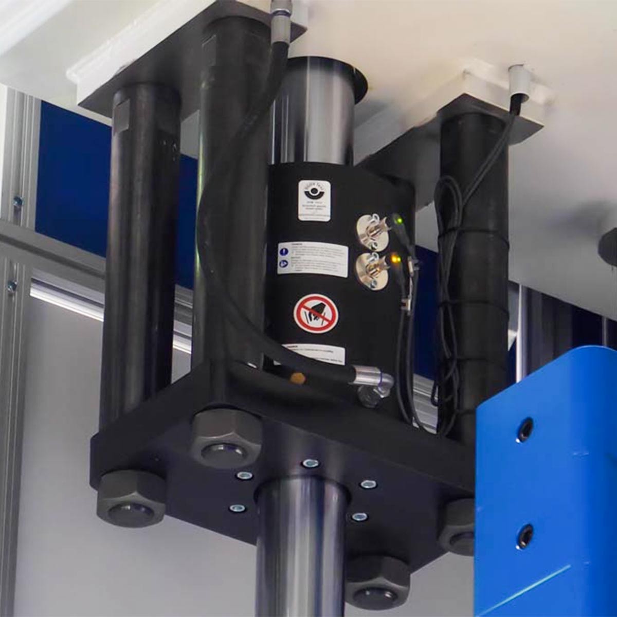
HYDROMECHANICAL SAFETY DEVICES AGAINST THE ACCIDENTAL FALL OF THE UPPER PLATE
2 hydromechanical fall prevention devices on the right and left sides of the press upper plate operating for the entire stroke length.
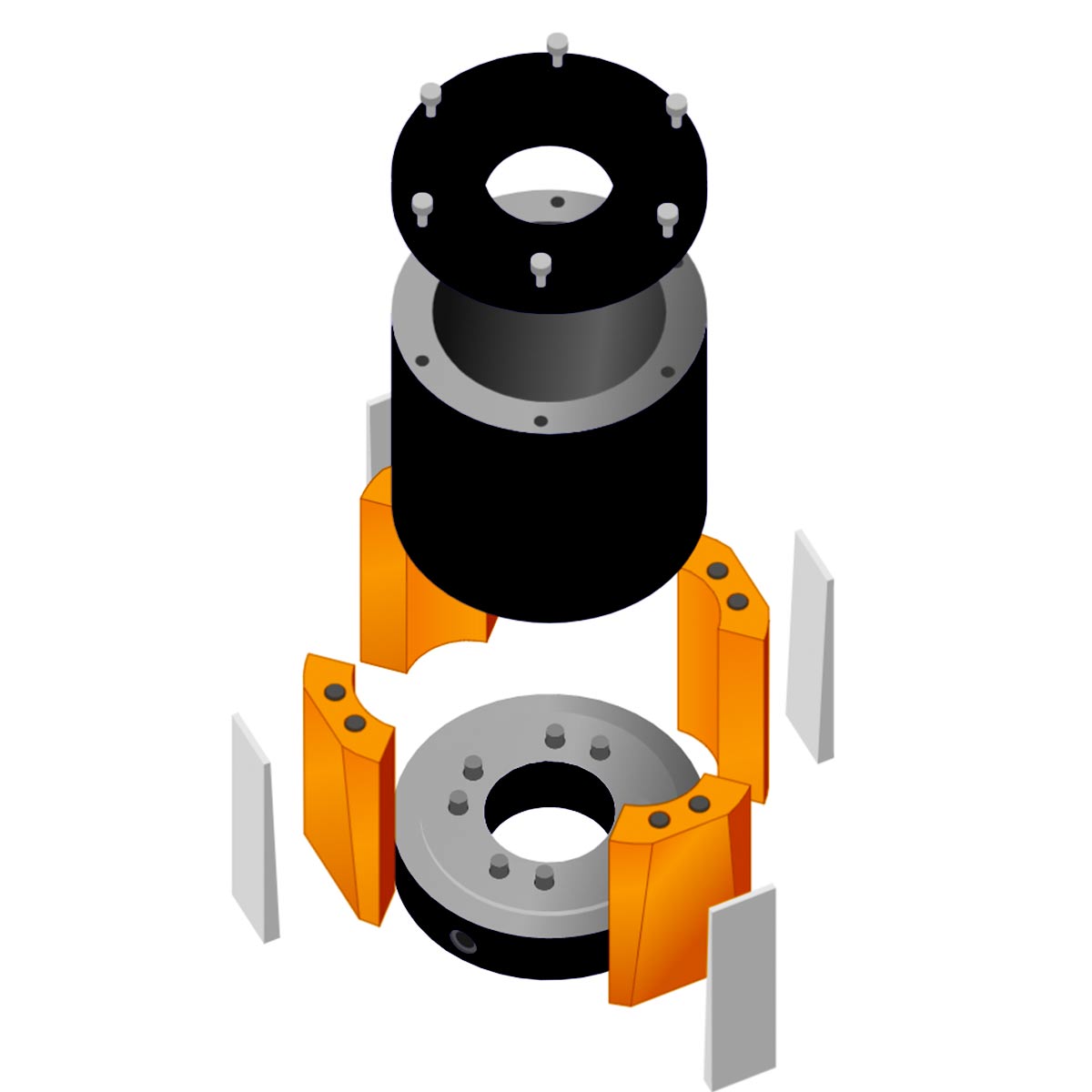
In case of hydraulic pressure drop, a patented device (SITEMA) guarantees an immediate motionless locking of the upper plate in case of hydraulic pressure drop.
Different from conventional multi-hole or toothed bars, this system prevents the press ram fall, in case of hydraulic system failure.
Function
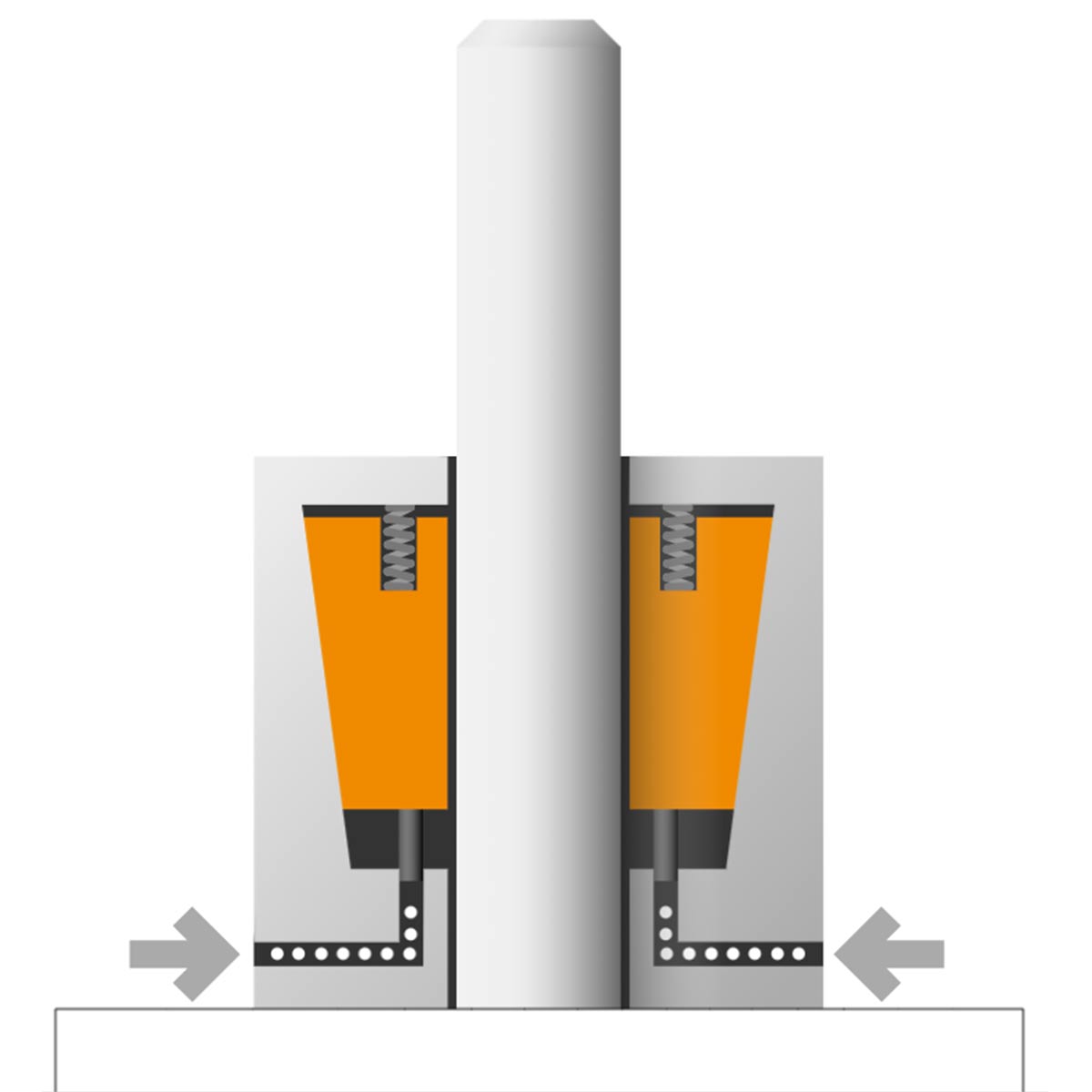
Step 1/6 Unlocked
The safety catcher is unclamped by pneumatic or hydraulic pressure applied to the annular piston. A well-defined clearance ensures the movement of the shaft, without friction. Proximity switch 2 active.
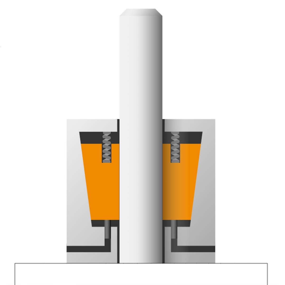
Step 2/6 Secure load
The Safety Catcher is activated as soon as pressure is released from the plungers.Then, the force of the springs allows the clamping jaws to contact the shaft firmly, thus securing the load. Signal change of proximity switch 2 to 1.
Step 3/6 Clamping
The clamping force, however, is not accumulated if the shaft has not been displaced by the load. By exploiting the static self-intensifying friction of the shaft, the jaws are drawn into the final clamping position at their mechanical stops.
Step 4/6 Load
If the load is increased further, the shaft remains in its position, until the static holding force is reached.
Step 5/6 Overload
As soon as this limit is exceeded, the locking device stops the movement of the rod, dissipating the kinetic energy of the falling mass.
Step 6/6 Release
Locking is released by an upward movement of the shaft and the simultaneous application of pressure on the locking device.
OPTIONAL EQUIPMENTS FOR THE MOULDS
Hydraulic ejection unit
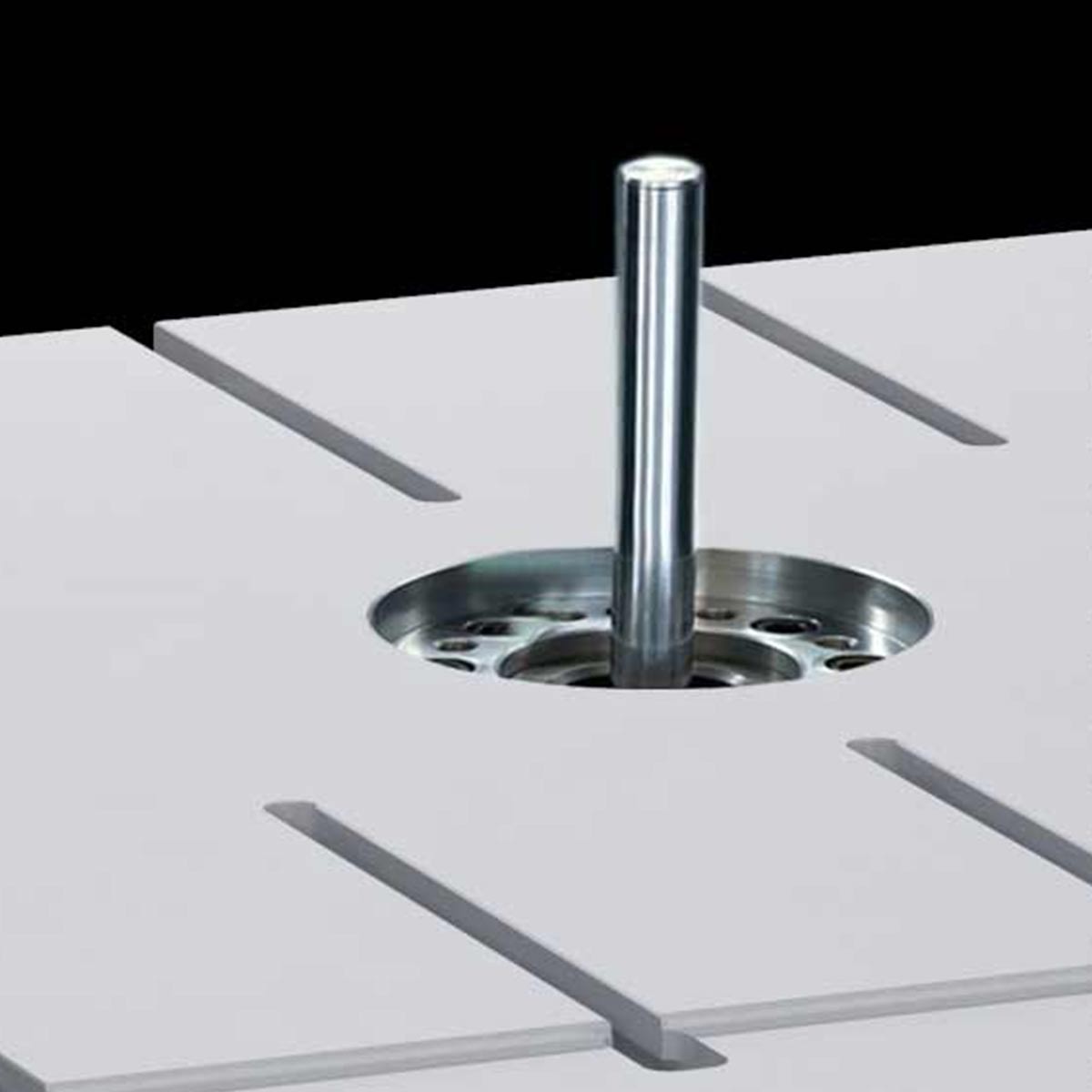
Hydraulic ejector cylinder in the lower plate (option)
The ejection unit initiates the movement of the ejection pins of dies and moulds for plastic materials and die casting.
This utility is made up of a hydraulic cylinder located in the middle of the press basement.
It allows to check and test some important mould functions in a very short time.
The pressure / thrust force is set by means of the il touch panel. The operating pressure depends directly on the line pressure. The advantage is the sensitive test of the mould ejection systems.
Hydraulic power unit
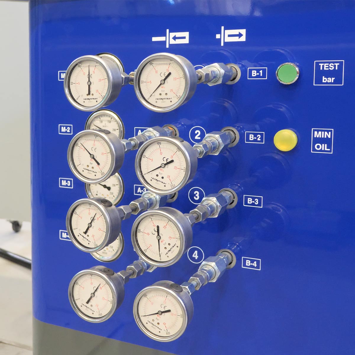
Separate hydraulic power unit on trolley with connections for hydraulic cylinders (4+4) (option)
A separate and standalone hydraulic power unit on trolley has been designed, in order to test the movements of slides and hydraulic cylinders. This trolley is equipped with a tank, and it is directly connected to the press control panel, with which it is possible to settle up to 4 pairs of hydraulic cylinders (4 inputs and 4 outputs), either individually or synchronously. Each connection pair is equipped with a standalone pressure regulator and an analogue pressure gauge.
The trolley can be provided in a completely stand-alone version with its own dedicated control panel, so that it can be used not only with the spotting press.
Upon the customer’s request, it is possible to configure the marks of the moulds with the spotting press, in order to test the correct functioning of the sensors and of the hydraulic cylinders. We can supply special cycles for the movement of slides/hydraulic cylinders.
The standard trolley is equipped with a pump with a delivery of 8 Liters/min. and a 2.2 kW engine. A customized trolley version is characterized by a pump with a delivery of 40 liters/min. and 11/15 kW engine. A special version for operation with water-glycol mix is also available.
SOFTWARE PROGRAM FOR AUTOMATIC CYCLES: QUALITY AND PROCESS OPTIMIZATION GUARANTEED
Millutensil developed a VERY INNOVATIVE SOFTWARE for testing the mould.
The operator can set a cycle and repeat it automatically multiple times.
The press will be equipped with a dedicated NEW SOFTWARE that enables operation in an automatic cycle for tasks such as making, automatic opening and closing movements, lapping or honing cycles.
For this purpose the press must be completely closed and equipped with light curtains on the open sides.(as tilting of upper platen and lower outdriving platen)
This automation allows the customer to optimize the adiustment process and automate functions that priviously required a significant aumount of time.
It ensures that the testing is carried out with sequential operations , enabling an effective and riliable final control test.
TECHNICAL ASSISTANCE
Diagnostic system
Integrated diagnostic system
MILLUTENSIL die & mould spotting presses are equipped with a specific and exclusive diagnostic program. Any failures occurred during operations is displayed on the control display, where the affected point is indicated. As a consequence, the machine downtime is minimized.
Main advantages:
- Minimization of down time,
- Quick and easy troubleshooting,
- Considerable service costs reduction, especially after the warranty period.
E-Won modem
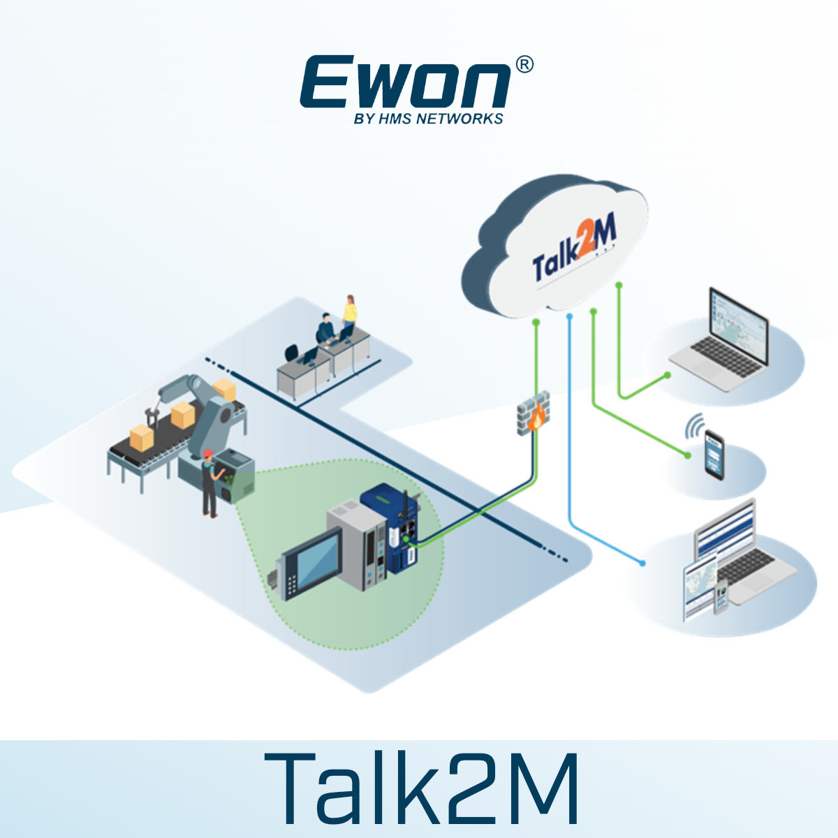
MIL-Series spotting presses are equipped with a E-Won modem, so that our Millutensil technicians can remotely operate on the spotting press to fix it.
The remote assistance can be easily performed thanks to the hotspot of a mobile phone and a password that is provided in case of need.
Wireless mobile panel
Thanks to the tablet Siemens multitouch ITP 1000 (optional) and its MyMILL© App (optional), remote assistance is simplified, since the tablet can be used to initiate the remote assistance call.
Training
For a complete use of the machine, we provide support and training to technicians during installation on site.
OPTIONAL ONLY FOR MIL CLASSIC
ROTATING TABLE
Extensible plate with integrated 0-90°-120°-180-240°-270° rotating table for multi-component moulds (option)
For the fitting of multi-component or multicolour moulds, the rotating table is fully integrated in the press lower plate.
Control is comfortably performed from the touch panel. Press plate rotation is possible either in the positions 0 ° -180 ° or in the positions 0 ° 90 ° -120 ° -180 ° -240 ° -270 °. After rotation into the two final positions, the rotating table is positioned and locked by means of a hydraulic cylinder.
The rotation movement occurs by means of a large bearing/articulate coupling, driven by an hydraulic motor.
Using the rotating table, it is possible to reduce the Min. and Max. opening between plates. With this option, the Min. and Max. opening between plates is automatically considered and adjusted to the original one.
The lower plate tilting by ±70° on the front / back side (option) is only possible when the rotating table is either in the 0° or in the 180° position.
The use of the integrated rotating table guarantees greater accuracy and completely avoids the manual rotation of the mould for its spotting, which takes quite some time.
TECHNICAL DATA
MIL CLASSIC 300 Series
| Description | MIL302 | MIL303 | MIL304 | MIL 305 | MIL 306 | MIL 307 | |
| – Size of press plates | mm | 3000 x 2000 | 3000 x 2000 | 3000 x 2000 | 3000 x 2400 | 3.500 x 2.400 | 3.500 x 2.500 |
| – Max. clamping force | kN | 2500 | 3000 | 4000 | 4000/5000 | 4000/5000 | 4000/5000 |
| – Max. opening force | kN | 700 | 800 | 850 | 900 | 1000 | 1000 |
| – Max. load capacity on lower plate | kg | 70000 | 70000 | 70000 | 75000 | 80000 | 80000 |
| – Max. load capacity on upper plate | kg | 25000 | 30000 | 30000 | 35000 | 40000 | 40000 |
| – max. opening between plates Vertical stroke: 180° on the PIT version |
mm | 300 – 2400
2100 |
300 – 2400
2100 |
300 – 2400
2100 |
400 – 2400
2800 |
400 – 2.8002.400 | 400 – 2.8002.400 |
| – Distance between columns | mm | 3200 | 3200 | 3200 | 3200 | 3700 | 3700 |
MIL COMPACT 3000 Series
| Description | MIL 3020 | MIL 3025 | MIL 3525 | MIL 3030 | MIL 3530 | |
| – Size of press plates | mm | 3000 x 2000 | 3000 x 2500 | 3500 x 2500 | 3000×3000 | 3500×3000 |
| – Max. clamping force | kN | 2500 | 2500 | 3000 | 3000 | 3000 |
| – Max. increased clamping force | kN | 3000 | 3000 | 4000 | 4000 | 4000 |
| – Max. opening force | kN | 900 | 900 | 1000 | 1000 | 1000 |
| >- Max. load capacity on lower plate | kg | 45000 | 50000 | 55000 | 60000 | 70000 |
| – Max. load capacity on upper plate | kg | 20000 | 22000 | 25000 | 30000 | 35000 |
| – Min. – max. opening between plates
– Vertical stroke: 180° pit version |
mm | 200 – 2.200 1700 |
200 – 2.500 2300 |
200 – 2.500 2300 |
200 – 2950 2750 |
200 – 2.950 2.750 |
| – Distance between columns | mm | 3100 | 3130 | 3600 | 3150 | 3650 |
Our worldwide references
