FOR ASSEMBLY, ADJUSTMENT, CHECKING AND REPAIR OF DIES
AM SERIES
The die-splitter was developed following our customers’ needs to easily handle big moulds, also in the sheet metal sector.
The die-splitter is an innovative, versatile and efficient solution, in line with the increasing automation of the manufacturing process and with the higher and higher safety standards.
Advantages of the AM series:
- Remarkable reduction of assembly and maintenance theme.
- Ergonomic positions for performing work on the dies.
- Extremely easy die handling.
All components are purchased from well-known manufacturers, such as for example: hydraulic system Bosch-Rexroth, Hawe; electrical system Siemens, Schneider Elektrik, Phoenix Contact, Weidmüller. This guarantees a general good functionality of the die-splitter, and a quick procurement all over the world.
EC Declaration of Conformity and compliance with safety provisions in accordance with the current EC standards.
PLATEN MOVEMENTS
For optimal access to the dies, the die-splitter upper plate can be rotated forward by 180° on the short side and blocked by four hydraulic wedges. In this way, the operator can work at an optimal height, normally standing on the dedicated platform on the front side of the die-splitter easily accessible through stairs.
Moreover, with rotation on the short side, the overall die-splitter height is considerably reduced. This means an advantageous working position, and at the same time maximum working safety
Hydraulic cylinders drive the lower extensible plate outside the columns in an easily accessible position for the work outside the die-splitter.
SOLUTIONS
SOLUTIONS FOR SMALL AND MEDIUM DIES
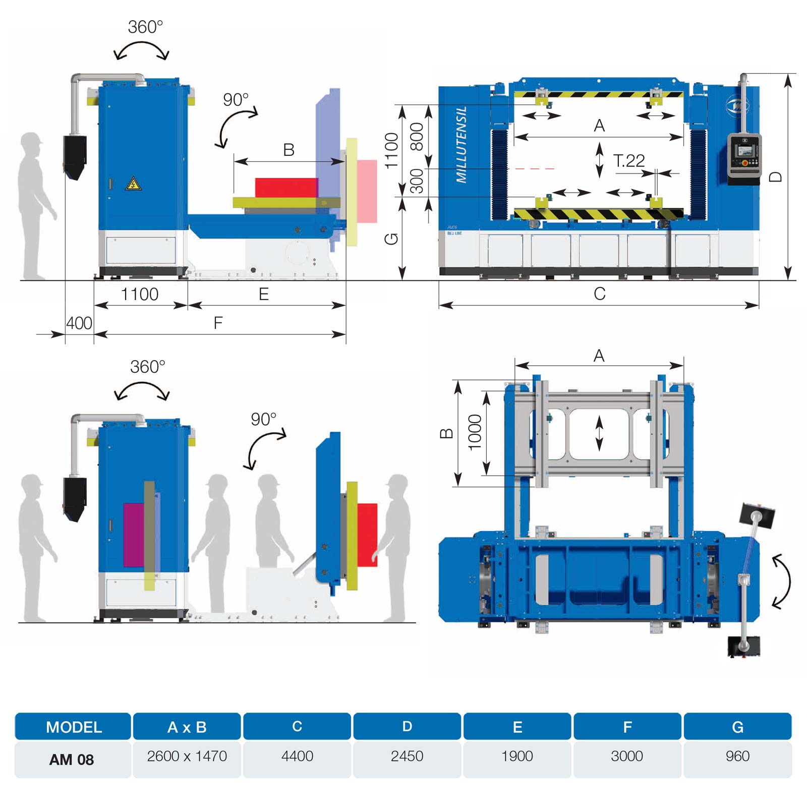
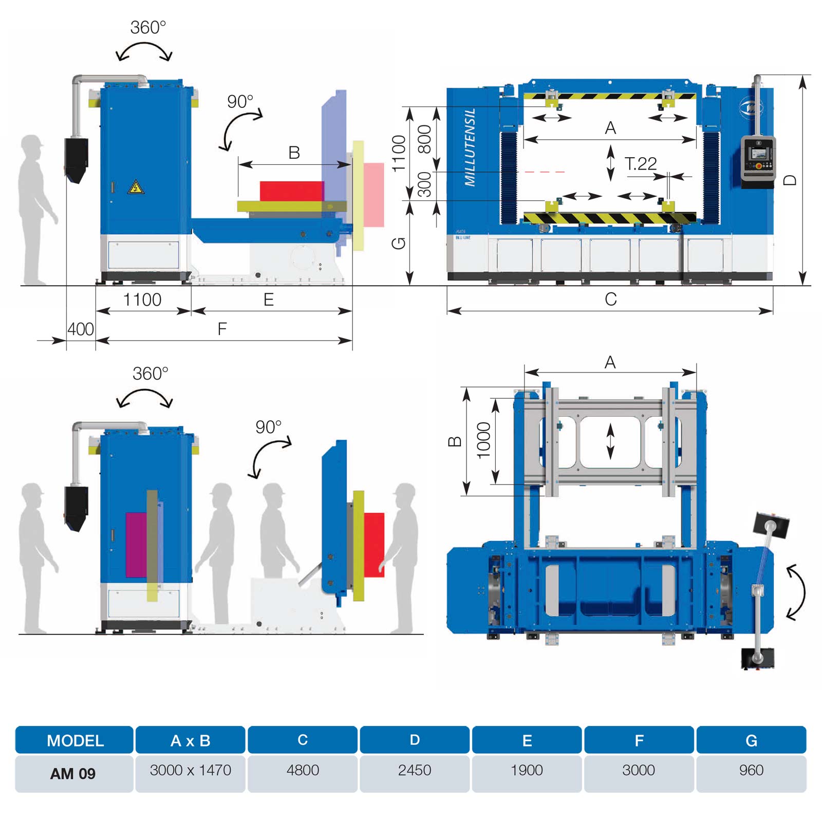
AM 04 | AM 06 | AM 08 | AM 09
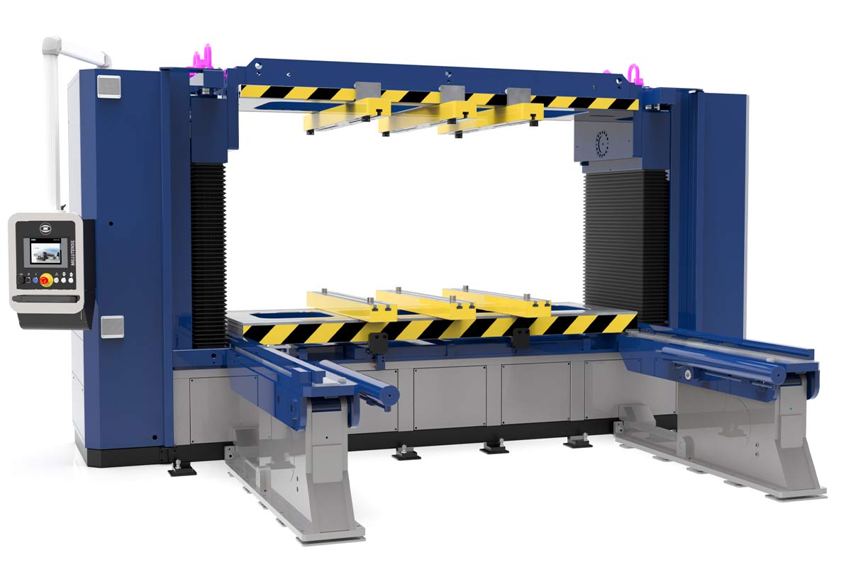
Die-splitter used for assembly, adjustment, checking and repair of dies for blanking, die casting, etc. with a very stable structure and a robust base made of welded, normalized steel.
The plates of the die-splitter have 2 large cavities that give the operator direct access to the lower parts of the die-halves, allowing rapid assembly and disassembly of the various parts of the dies.
The lower plate is removable and slides on the base plate via ball bearings and is hydraulically actuated to move the lower part of the die outward (to the back of the die-splitter), rotated by 90° to provide access to any part of the half-die. As the removable plate returns back to its initial position, it stops mechanically and precisely, to ensure perfect repositioning, along with repeatability of the die halves’ closure.
The hydraulically actuated upper plate slides vertically on four guide columns and can rotate by 360° by reduction gears, to bring the upper die half in a comfortable position for working on it. The clamping of the upper plate in the exact horizontal position is ensured by four hydraulically actuated locating pins.
Click and drag to rotate the view. Scroll to zoom.
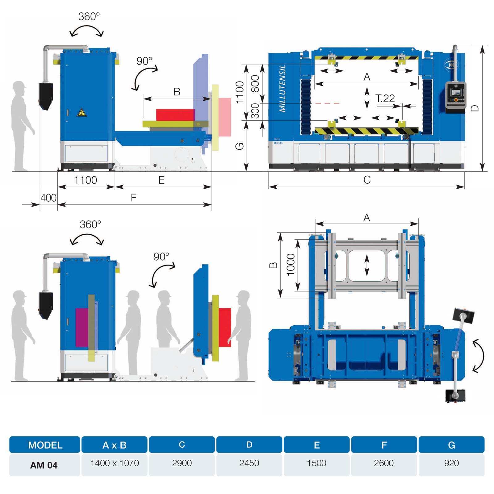
AM 04 – Platens dimension 1400×1070 mm
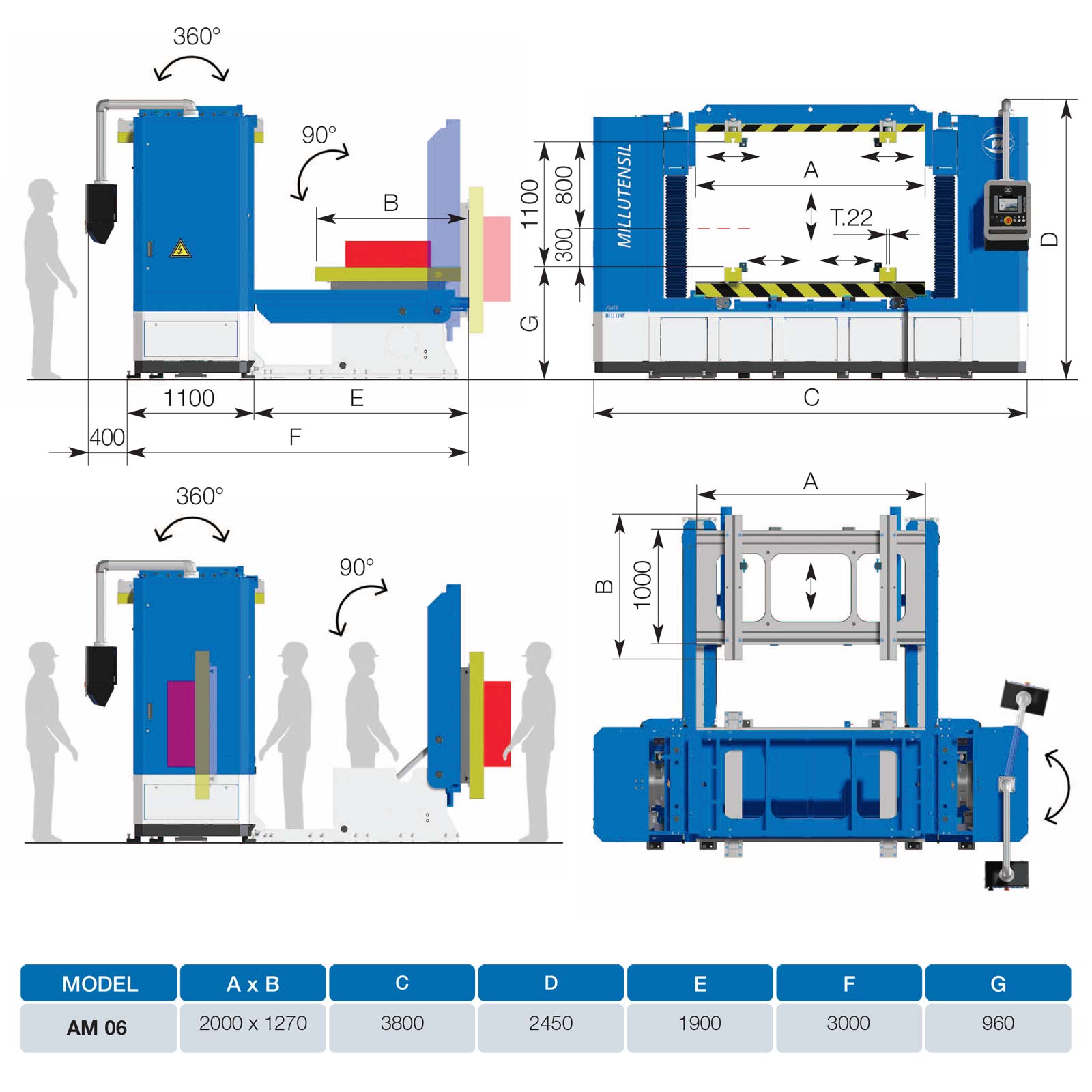
AM 06 – Platens dimension 2000×1270 mm
AM 08 – Platens dimension 2600×1470 mm
AM 09 – Platens dimension 3000×1470 mm
VIDEO
FEATURES
Structure
- Die-splitter with 4 chrome-plated, alloy steel columns, structures made of welded and normalized steel, and a sturdy cast iron baseplate to guarantee high rigidity and bending resistance.
- Basement embedded in a robust arc-welded structure, that is highly rigid and flexion-proof
- Orthogonality assessment of the upper platen thanks to a Millutensil patented system made up by four wedges that guarantee high precision
- Very long maintenance-free ram precision guides, with bronze bushings lubricated for life with teflon coating. They guarantee high rotation stability and ram repeatability precision
CONTROL PANEL
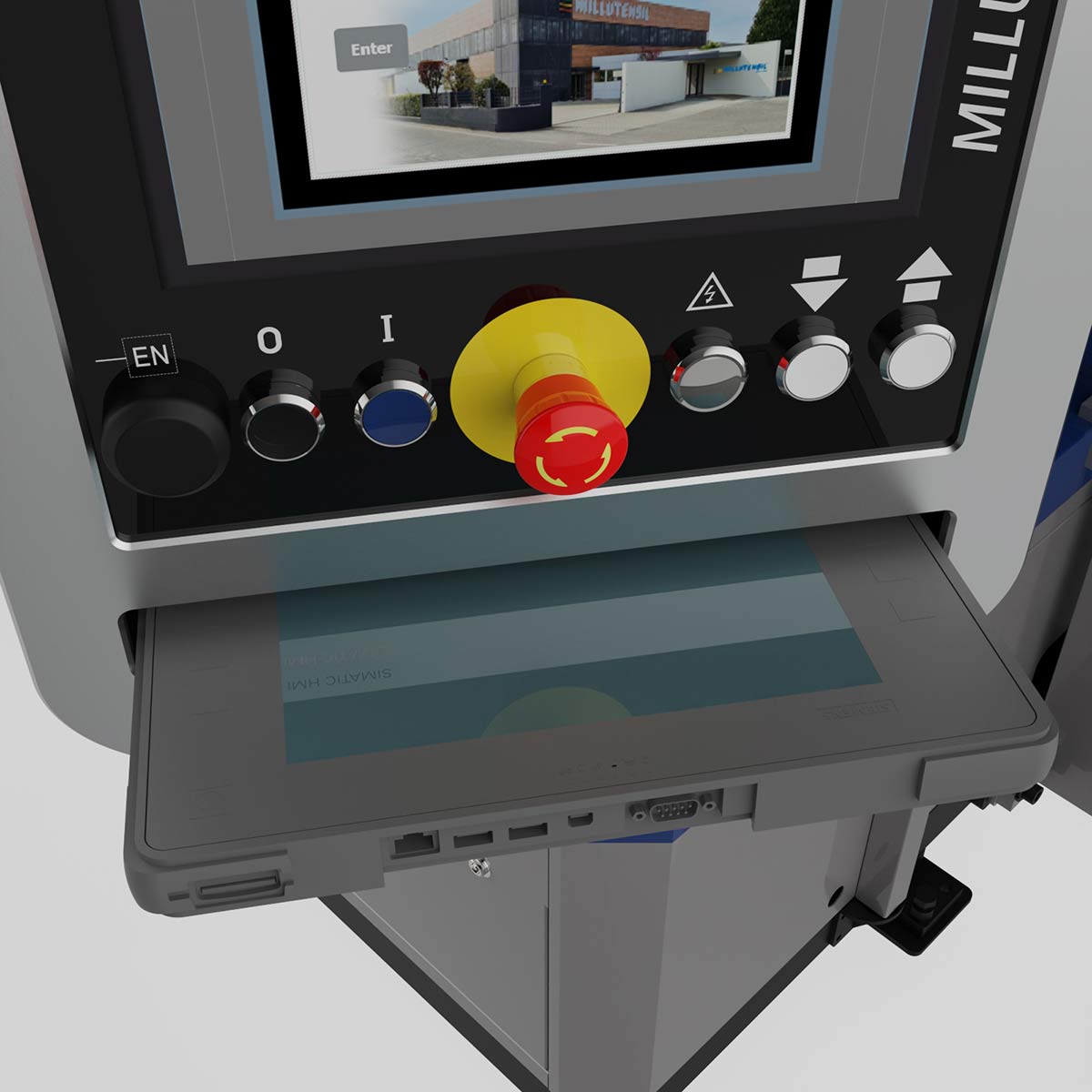
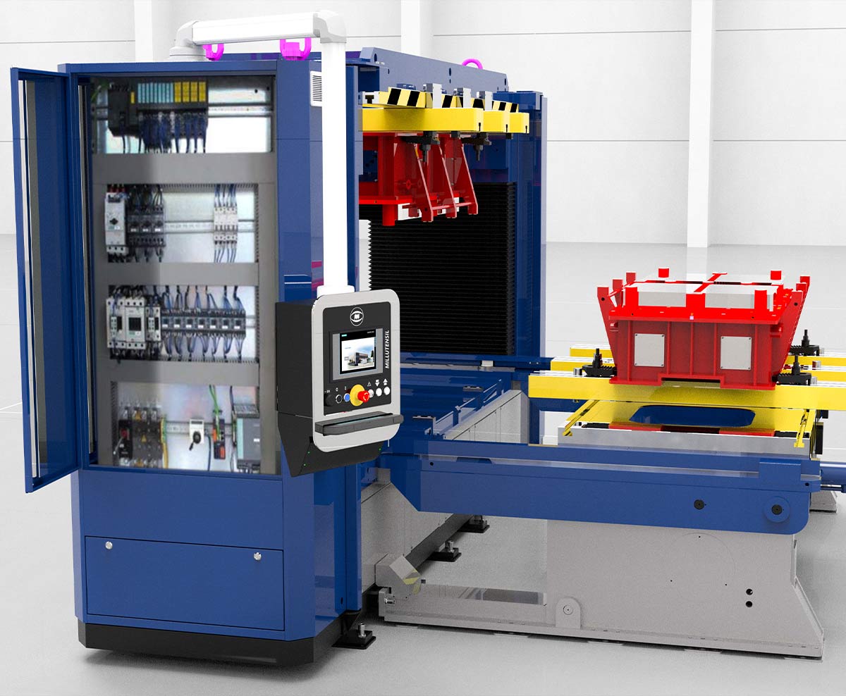
TOUCH PANEL FOR AM – AMS SERIES
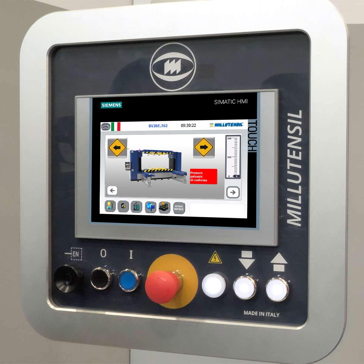
Uncluttered, clear and ergonomic, the panel offers many advantages as well as vast flexibility in customizing features.
Siemens S7-1500 control easy to program and use.
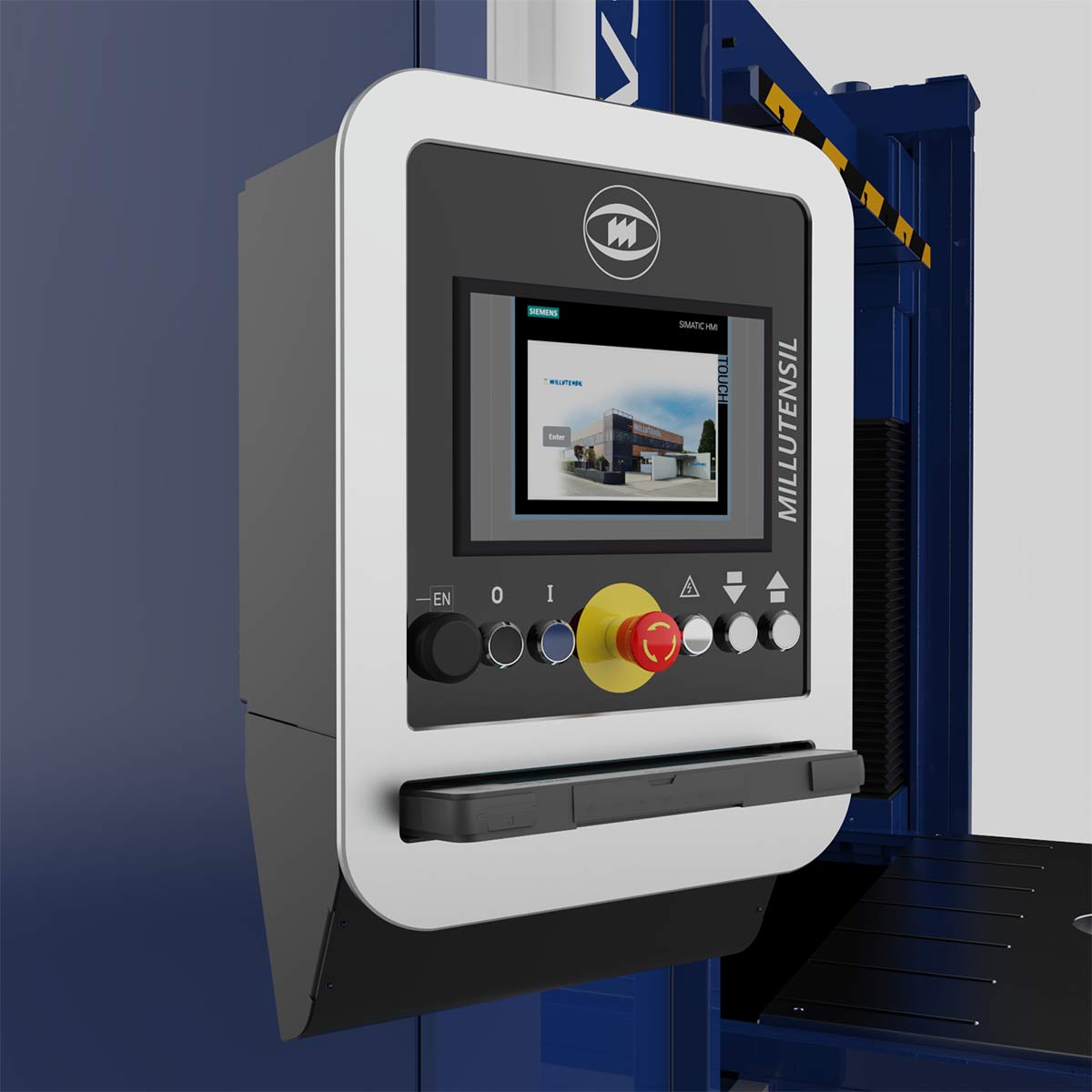
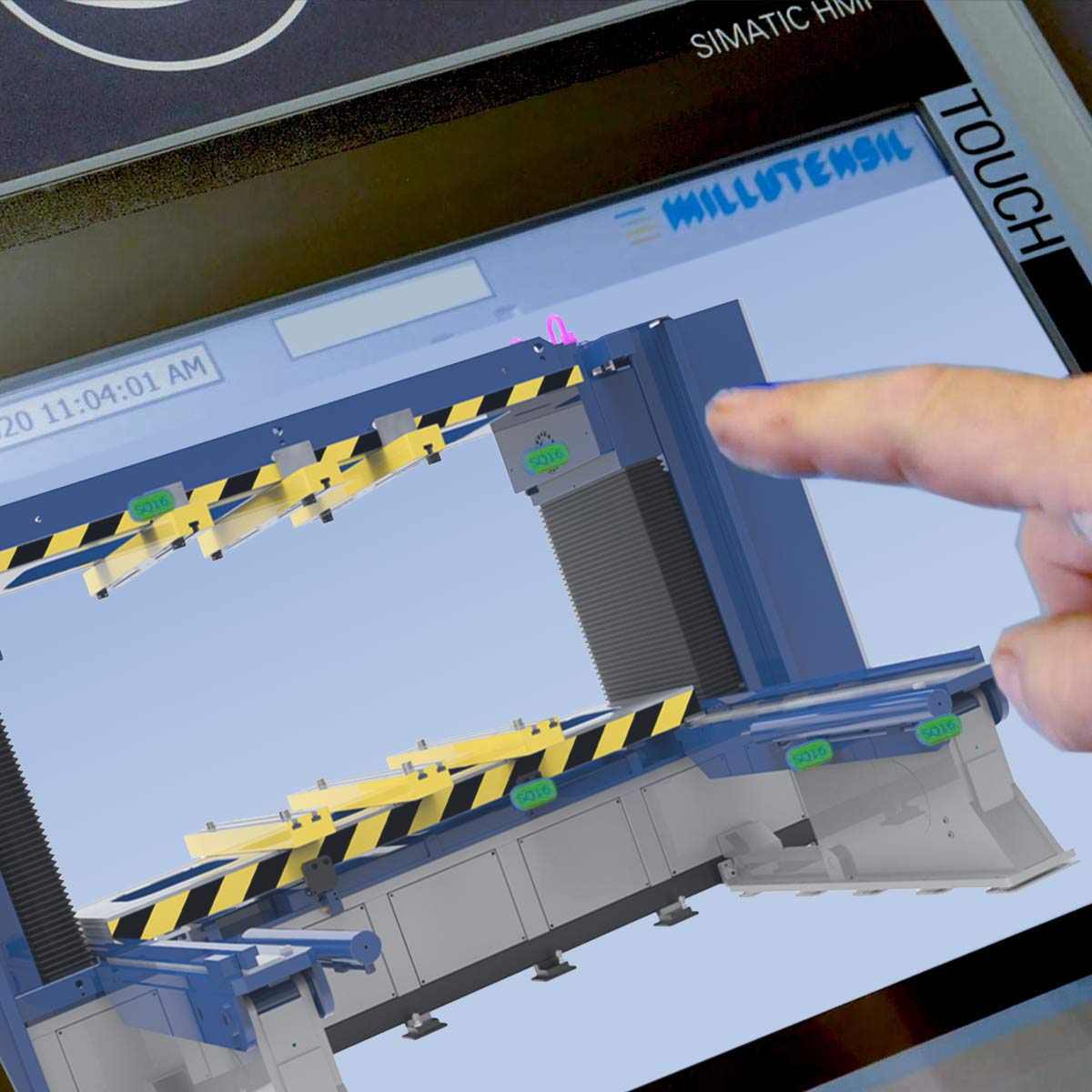
The control panel is equipped with a touch panel with user-friendly graphics to simplify the use of the die-splitter. Due to security reasons, some functions can be activated only through traditional buttons (i.e. the downstroke has to be performed with two-hands in accordance to the EU safety legislation).
The control panel is mounted suspended on the die-splitter right side and can also be rotated to the back so that it is even easier to use for the operator.
Two-hands command.
Due to security reasons, some functions can be activated only through traditional buttons (i.e. downstroke must be carried out with two-hands, in compliance with EU-UL-CSA safety legislation).
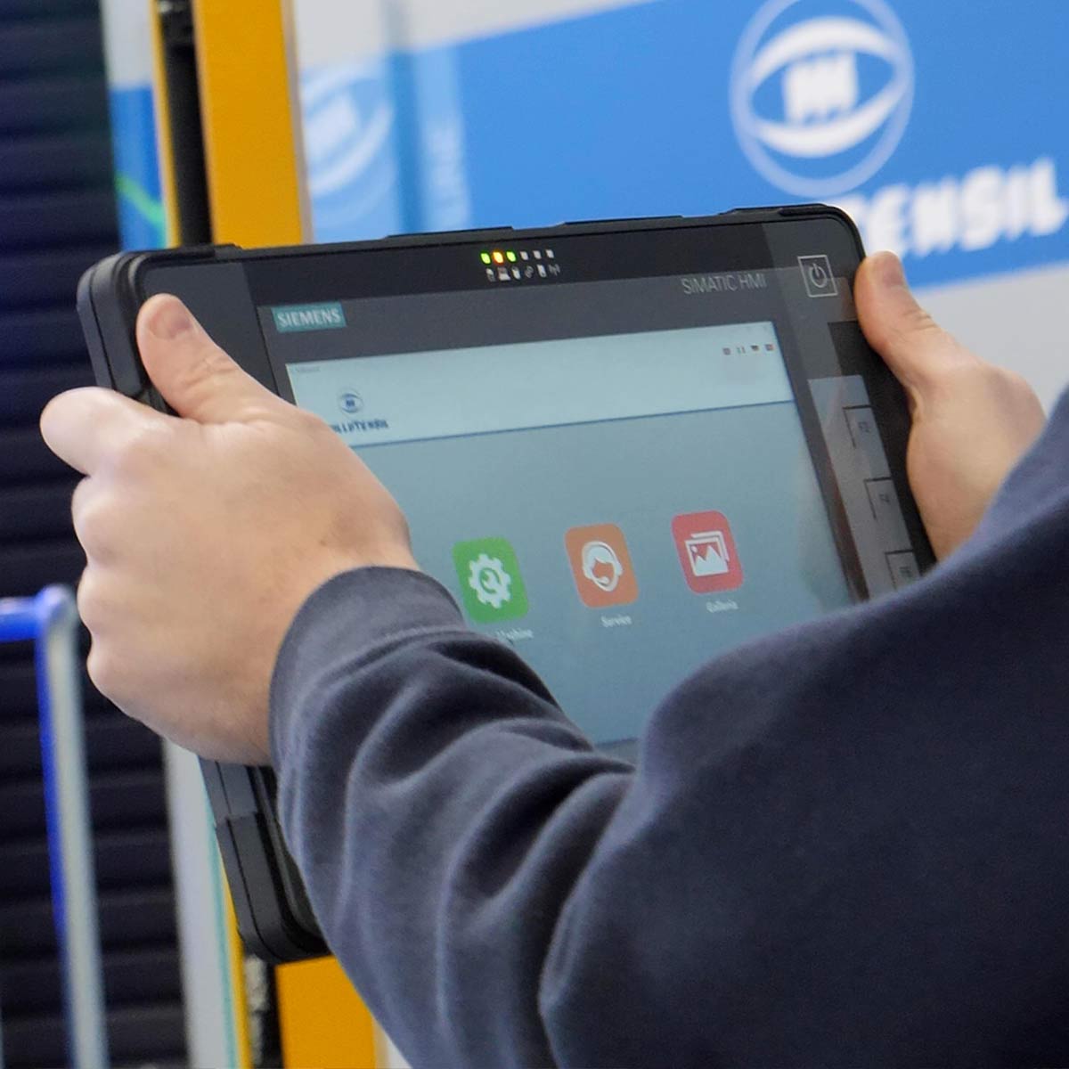
In the pulpit station a new Siemens multi-touch ITP 1000 can be embedded (OPTIONAL).
This new Siemens multi-touch ITP 1000 is supported by a dedicated app called MyMILL© App, that has been developed by Millutensil as a result of the ongoing cooperation between Millutensil and their customers.
EQUIPMENTS FOR THE DIE-SPLITTERS
ELECTRONIC MANAGEMENT OF THE UPPER PLATE UP/DOWN STROKE OF AM DIE-SPLITTERS
(AM04 | AM06 | AM 08 | AM 09)
The upper plate up/down stroke is based on a fully electronic management of the main hydraulic system, which through special proportional servo-valves controls and manages, with maximum accuracy, the oil flow generating the parallel movement of the 2 up/down stroke cylinders.
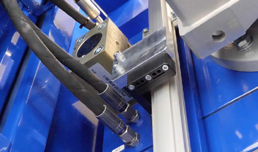
Movement is monitored by means of absolute linear Encoder with magnetic codification.
The device fully manages the synchronized movement of the two up/down stroke cylinders which move the die-splitter upper plate.
ELECTRONIC UPPER PLATE PARALLELISM ANTI-UNBALANCE SAFETY DEVICE
(AM04 | AM06 | AM 08 | AM 09)
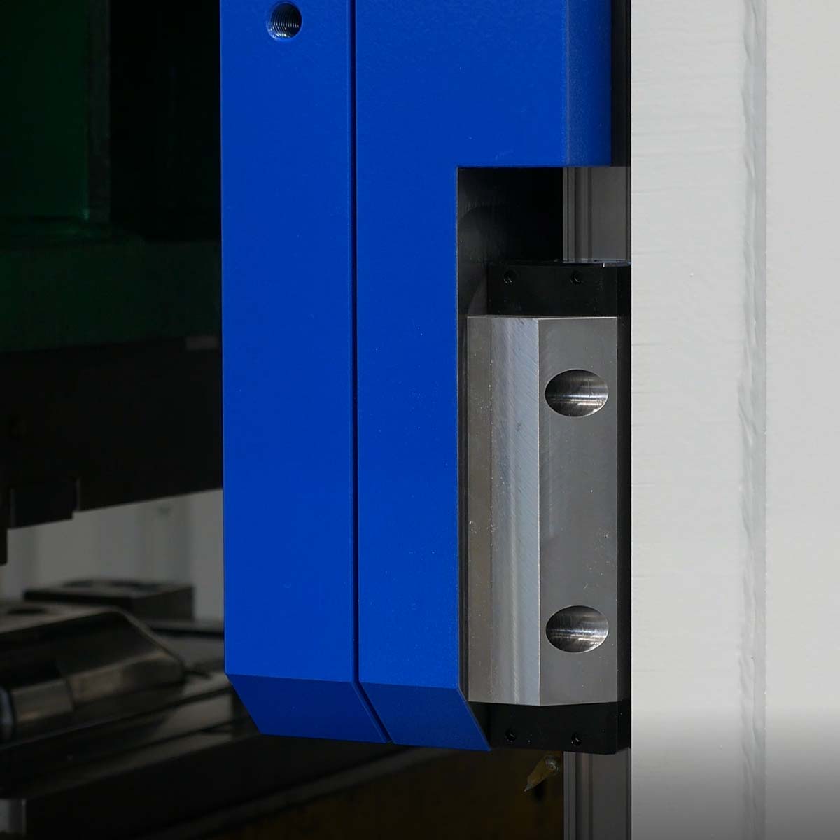
The control system includes measurement devices (absolute linear Encoder with magnetic codification), which continuously check the die-splitter upper plate position and parallelism compared to the lower plate.
The value is dynamically displayed on the touch panel for the entire stroke.
Using this system both the die-splitter and dies are protected from possible damage.
green mode
By means of a special low-pressure circuit, oil is sucked from the tank. This allows a higher speed, without heating the oil, with a definitively low energy consumption.
After 100 seconds out of service, the hydraulic unit turns off in order to save energy. By pressing the specific push-button, the group is activated and hydraulic pressure is immediately restored.
OPTIONAL EQUIPMENTS FOR THE DIES
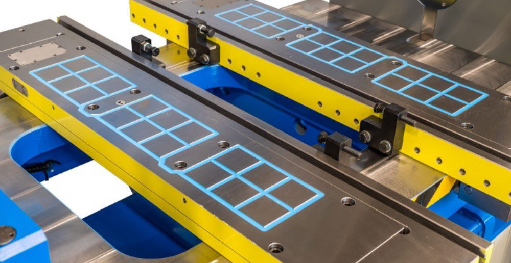
MACHINE PLATENS WITH PERMANENT MAGNETS
For fast die clamping – available according to model and capacity.
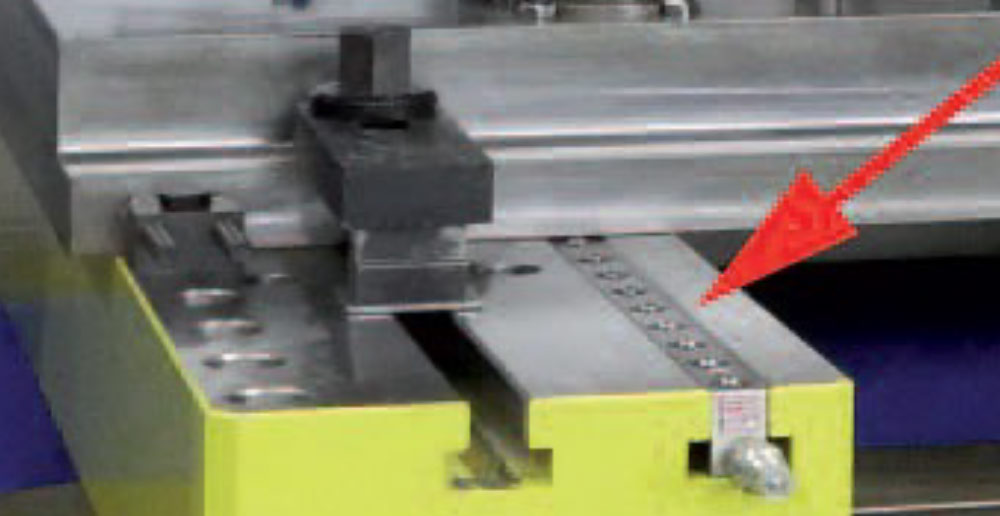
DIE HOLDING BEAMS WITH HYDRAULIC BALL INSERTS
They facilitate manual centering and coupling of the two half dies after possible disassembly.
CENTERING BLOKS
Centering blocks that are used when only half of the mold is dismantled for maintenance
They are mechanical references to recenter the other half of the mold.

TECHNICAL ASSISTANCE
Diagnostic system
Integrated diagnostic system
MILLUTENSIL die-splitters are equipped with a specific and exclusive diagnostic program. Any failures occurred during operations is displayed on the control display, where the affected point is indicated. As a consequence, the machine downtime is minimized.
Main advantages:
- Minimization of down time,
- Quick and easy troubleshooting,
- Considerable service costs reduction, especially after the warranty period.
E-Won modem
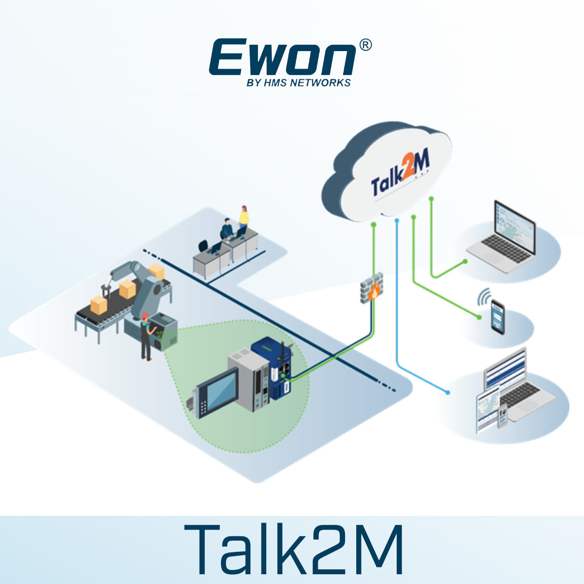
MILLUTENSIL die-splitters are equipped with a E-Won modem, so that our Millutensil technicians can remotely operate on the die-splitter to fix it.
The remote assistance can be easily performed thanks to the hotspot of a mobile phone and a password that is provided in case of need.
Wireless mobile panel
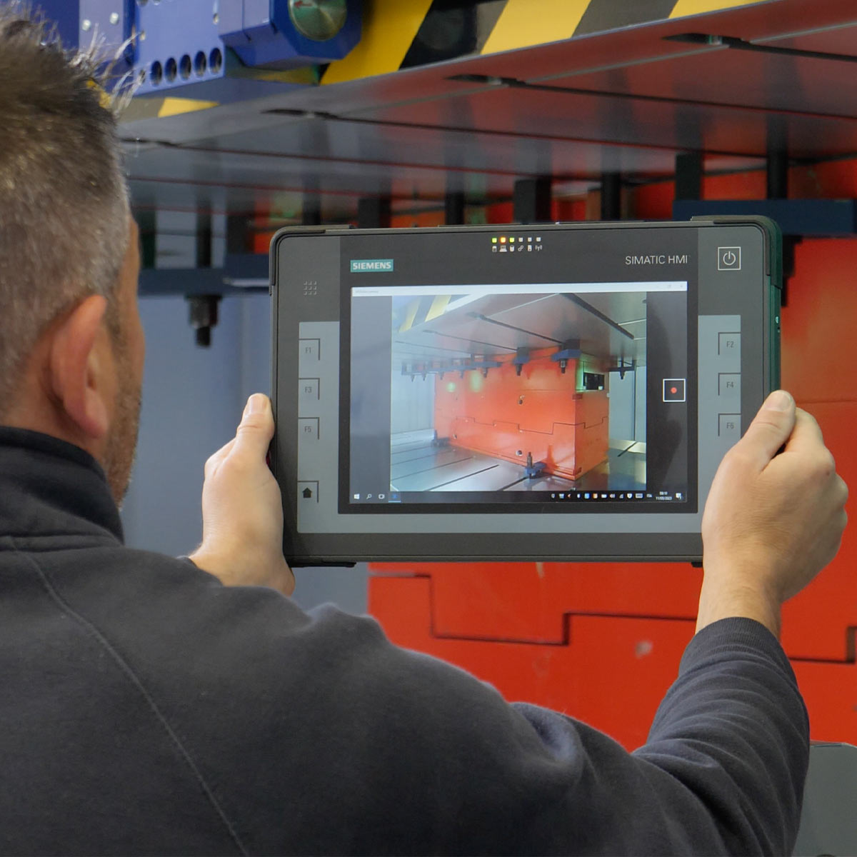
Thanks to the tablet Siemens multitouch ITP 1000 (optional) and its MyMILL© App (optional), remote assistance is simplified, since the tablet can be used to initiate the remote assistance call.
Training
For a complete use of the machine, we provide support and training to technicians during installation on site.
TECHNICAL DATA
| Description | AM 04 | AMS 06 | AMS 08 | AM 09 | |
| Size of press plates | mm | 1400x 1070 | 2000 x 1270 | 2600 x 1470 | 3000 x 1470 |
| Min opening between plates | mm | 300 | 300 | 300 | 500 |
| Max opening between plates | mm | 1100 | 1100 | 1100 | 1100 |
| Max. load capacity on lower plate | kg | 4000 | 6000 | 8000 | 9000 |
| Max. load capacity on upper plate | kg | 1500 | 3000 | 3500 | 4000 |
LAYOUT
Our worldwide references
